Motorsports · Nov 2023
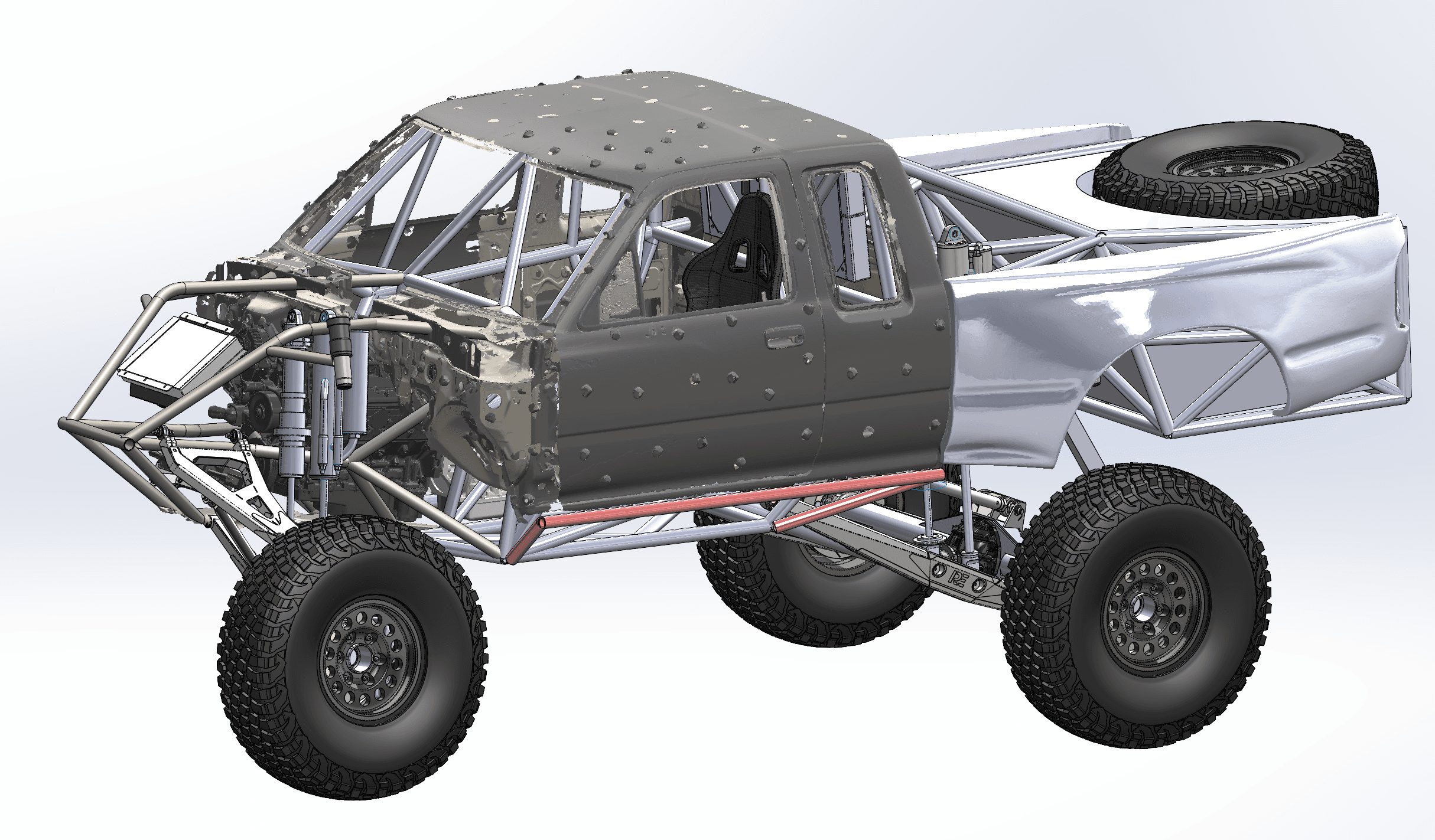
Trophy Truck Chassis Designed Around a 3D-Scanned Cab
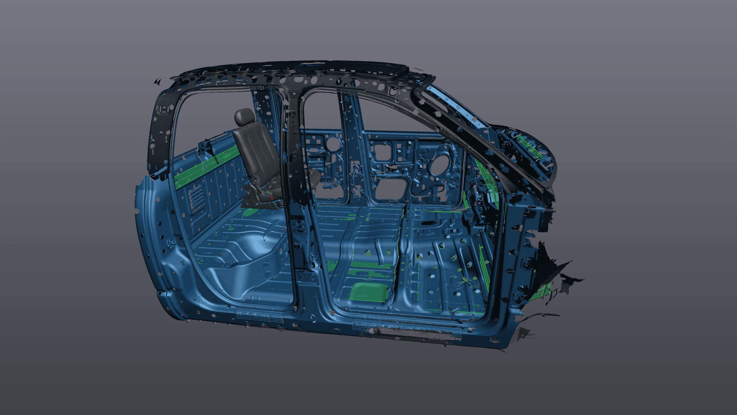
An extra-cab pickup cab and front clip were 3D scanned, then a full tube chassis, cage and long-travel suspension were designed around the mesh in CAD.
Reverse Engineering & Scan-to-CAD
What you get
Holes are true cylinders, flat faces are flat and every feature has a dimension you can change. Your team opens the STEP file and keeps designing instead of fighting a mesh.
We agree up front whether the model should match the part exactly as it is, worn spots and all, or capture the clean geometry it was meant to have. Many jobs mix the two: as-built where it mounts, idealized everywhere else.
Models are clean solids that drop straight into CAM, sheet-metal and 3D-printing workflows, in neutral formats your shop already reads.
Our founder, Joshua Frey, holds a B.S. in Mechanical Engineering from the University of Nevada, Reno and has designed trophy trucks and high-performance off-road vehicles. Need a bracket, mount or full chassis around the scanned part? We design that too.
Process
We start with what the model is for: a replacement part, a revised design, a mating part or a reference for a larger assembly. That decides which features are critical and how closely each surface must follow the scan.
We scan it in Reno or on site, with extra coverage on mounting faces, bores and hole patterns, because those drive the model.
Planes, cylinders and axes are fitted to the mesh to pull out tube diameters, bore centers, bolt patterns and datum faces. On a solid-axle swap, this is how we located the axle tubes and ball-joint bosses before designing links and brackets.
Features are sketched and built against the scan: extrudes, revolves and sweeps for machined and fabricated shapes, surfaces for freeform areas. We check the model against the mesh as we go so nothing drifts.
You review the model, we make agreed revisions, and you receive STEP, Parasolid (X_T) or IGES files along with the scan mesh.
Typical jobs
Discontinued, hand-made or imported parts where no print exists. We model what's there so you can remake it, modify it or send it out for quotes.
Scan the best surviving example, then model it back to its intended shape so the new part fits the way the original was meant to.
Brackets, bumpers, adapters and housings have to fit something that already exists. Scanned mounting points let you design to the actual hole positions from the start.
We've designed a trophy-truck tube chassis around a scanned cab, and long-travel front suspension around a scanned differential and steering rack.
Start from the scanned original, then lengthen, strengthen, lighten or add features in a model you can keep editing.
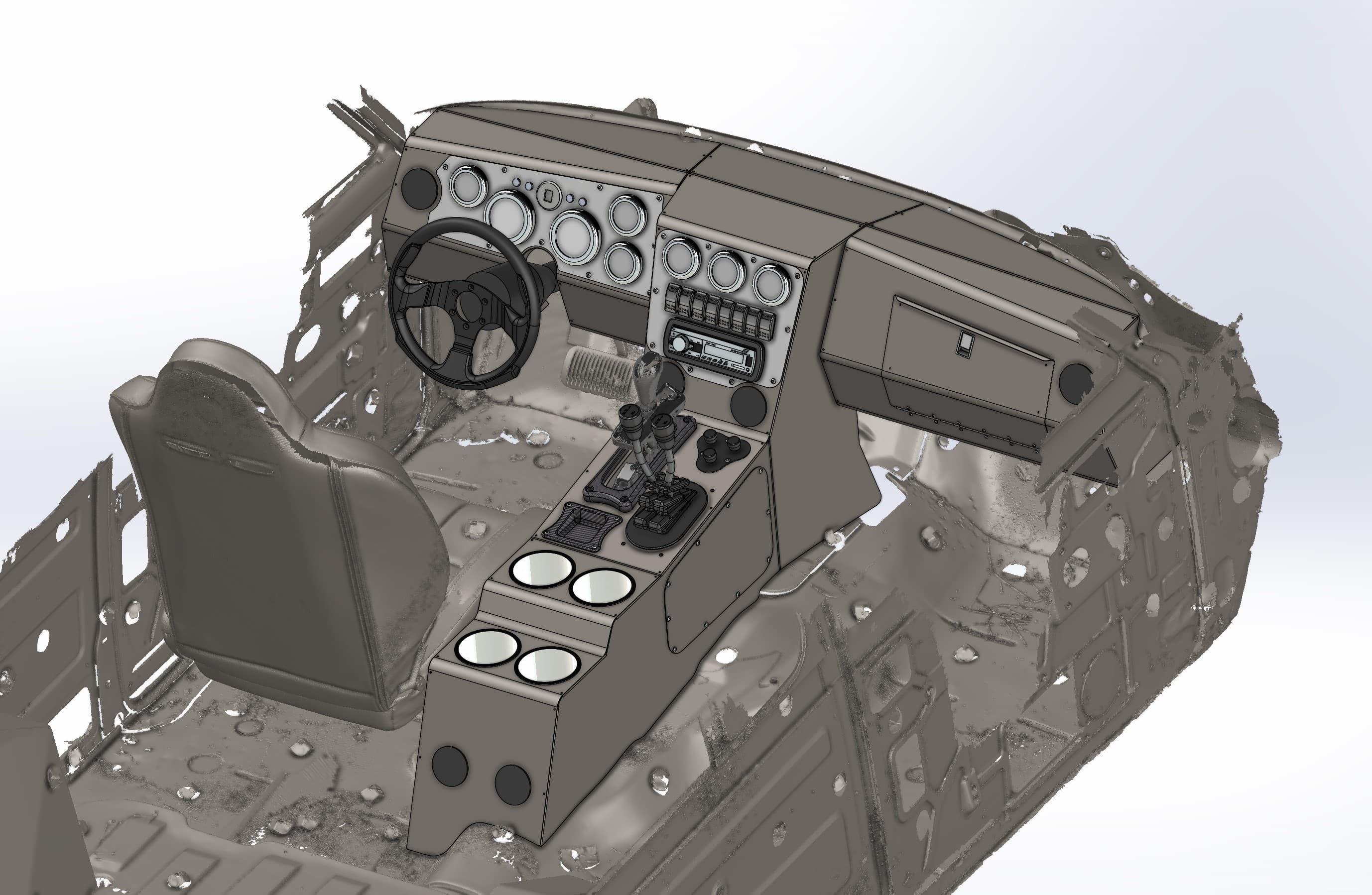
Interior parts drawn against a scanned cab or cockpit follow the real sheet metal and structure, including the dents and variations no factory drawing shows.
Proof
Motorsports · Nov 2023
An extra-cab pickup cab and front clip were 3D scanned, then a full tube chassis, cage and long-travel suspension were designed around the mesh in CAD.
Automotive · Jul 2025
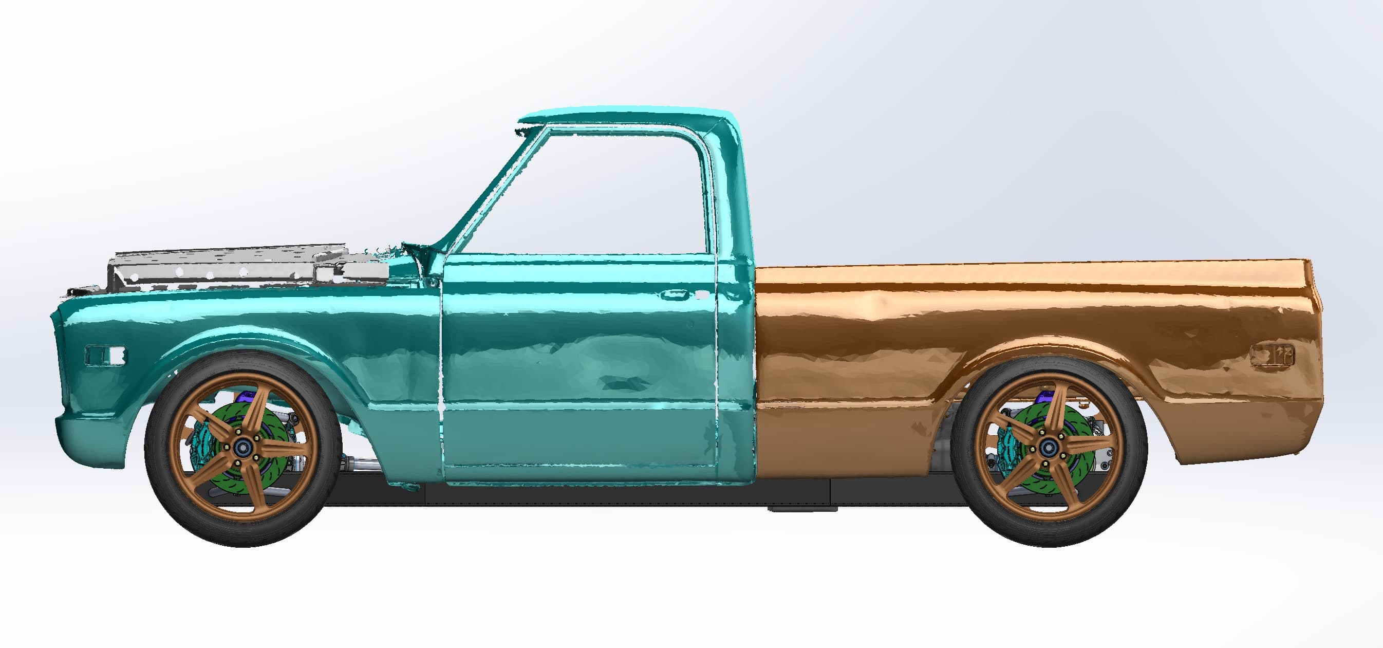
A '67–72 Chevy C10 body was 3D scanned, then a mid-engine, all-wheel-drive chassis was designed in CAD around the real cab, front clip and bed.
Automotive · Jun 2023
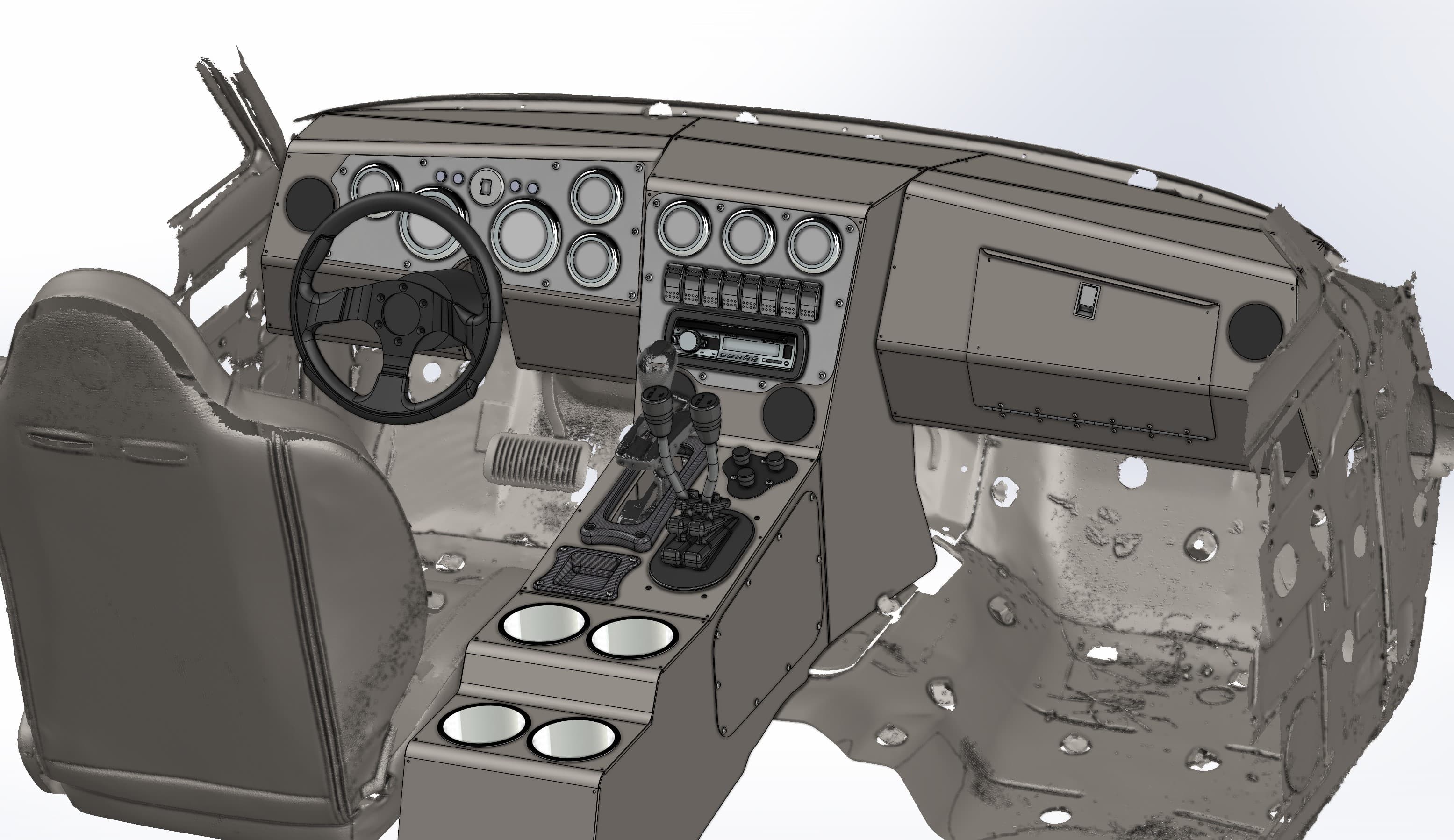
A stripped vintage 4x4 cab was 3D scanned, then a custom dash with gauges and switches and a matching center console were designed in CAD to fit it.
FAQ
Scan-to-CAD is turning a 3D scan mesh into a solid CAD model. The scan supplies the shape, and an engineer rebuilds it as features you can edit, dimension and manufacture.
Yes, but not by changing the file type. A mesh exported straight to STEP is still a pile of triangles that won't edit properly, so we rebuild it as true solid features and then export STEP, X_T or IGES.
Yes, that's the usual situation. The scan replaces the missing print, and you end up with a CAD model, plus 2D drawings if you need them.
It matches as closely as the job needs. We agree which features must follow the scan exactly and which should be modeled to clean design intent, then check the finished model against the mesh.
We model in SolidWorks and deliver STEP, Parasolid (X_T) or IGES, which open in SolidWorks, Fusion, Inventor, Creo, NX, CATIA and most other CAD packages.
It depends on how many features the part has and how much design work is involved. Start with the instant estimate, or send photos and request a quote.
Guides
Reverse Engineering · 6 min read
How scan-to-CAD reverse engineering works: point cloud to mesh to SolidWorks model, design intent vs. as-built, output formats, and when a mesh is enough.
Technology · 6 min read
STL vs. STEP for 3D scan deliverables: what a mesh is, what CAD is, a side-by-side table, and which file you need for printing, machining, molding or design.
Guides · 6 min read
What drives 3D scanning cost: size, surface finish, deliverable, location and quantity. See typical scan times, ways to lower your price and get an estimate.
More services
Start a project
Tell us the size, complexity and what you need back. The instant estimate gives you a budget range now. Then we review the details and send a firm quote.