Scan-to-CAD reverse engineering turns a physical part into a CAD model you can use. A 3D scanner measures the surface as millions of points, software turns those points into a mesh, and an engineer rebuilds the part in CAD using the mesh as a measured reference. You end up with a STEP, Parasolid or IGES file you can edit, machine from or design new parts against.
The scanning is the easy part to explain. The engineering is in the modeling: deciding which features matter, whether to model the part as it was designed or as it exists today, and how much CAD you actually need. This guide walks through each step the way we run it in our reverse engineering service, with examples from our own motorsports work.
Step 1: capture the point cloud
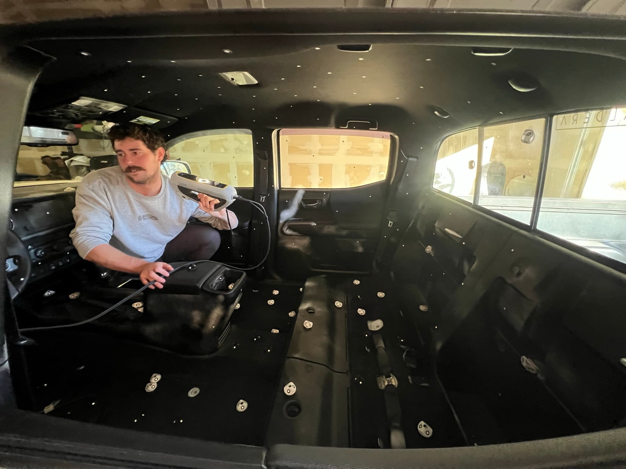
We scan with handheld blue-laser and structured white-light scanners. Small reflective positioning targets go on or around the part so the scanner always knows where it is. Shiny, dark or clear surfaces get a light coat of sublimating scanning spray, which disappears on its own afterward.
Each measurement is a point with an X, Y and Z coordinate on the surface. Together they form a point cloud. The scanner only records what it can see, so this is where planning matters: remove whatever hides the features you need, and make sure every critical surface gets a clear line of sight. Our scanners are specified at accuracy up to 0.03 mm (0.0012 in). How close a real job gets to that depends on the part's size, surface and setup.
Step 2: build and clean the mesh
The scan software connects the points into a polygon mesh of small triangles, saved as STL, OBJ or PLY. Before modeling, the mesh needs work:
- Trim stray data like the floor, stands and fixtures.
- Fill small holes, including the spots where targets sat.
- Reduce the triangle count where the surface is simple, while keeping detail on edges and features.
- Align the mesh to a coordinate system that means something, such as a vehicle centerline, the frame rails, an axle centerline or a part's mounting face.
Alignment is underrated. A model built on well-chosen datums drops straight into your assembly. One built on the scanner's arbitrary origin has to be fixed later by everyone who opens it.
Step 3: extract planes, cylinders and holes
Next we fit exact geometry to regions of the mesh: planes to machined faces, cylinders to tubes, bores and shafts, circles to hole edges, and axes through all of them. A fitted cylinder uses thousands of points at once, so it is far more reliable than a single caliper reading on a worn tube.
These fitted features become the reference geometry in SolidWorks. Every sketch and every mounting point in the CAD model ties back to them.
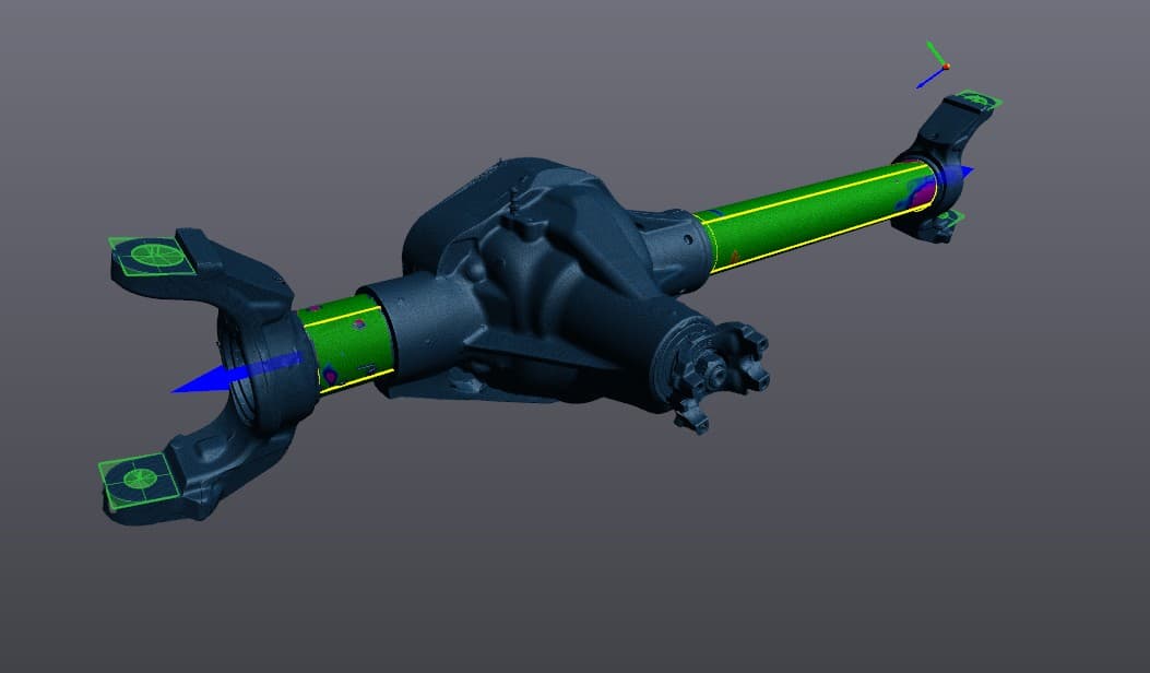
On our 1st-gen Tacoma solid-axle swap, that's how the front axle housing went from scan to design input. The fitted tube axes and knuckle planes set the geometry the new suspension was designed around.
Step 4: choose surfacing or parametric modeling
There are two ways to turn a mesh into a solid, and most real jobs use a mix of both.
Surfacing
Auto-surfacing wraps the mesh in a patchwork of NURBS surfaces (smooth, mathematically defined surfaces) and stitches them into a solid. It is quick and handles freeform shapes well: body panels, castings, sculptures, ducting. The tradeoff is that the result has no feature history, and it carries every dent and ripple from the scan. Changing a hole size later means surgery, not editing a dimension.
Parametric solid modeling in SolidWorks
Here the part is rebuilt the way a designer would build it from scratch: sketches, extrudes, revolves, holes and fillets, each referenced to the fitted features from step 3. The model has a feature tree, clean dimensions and real design logic. It takes longer, but it is the right choice for machined parts, brackets, housings and anything you will change, make drawings from or send out for manufacturing.
| Surface model | Parametric solid | |
|---|---|---|
| How it's built | NURBS patches fit to the mesh | Sketches and features referenced to the scan |
| Match to the scan | Close, including dents and wear | To the features you model, with clean dimensions |
| Editable | Hard, no feature history | Yes, through the feature tree |
| Best for | Freeform shapes | Machined and fabricated parts |
| Effort | Lower | Higher |
A hybrid is common: parametric features for mounting faces, holes and bores, with surfaces for the freeform areas between them.
Design intent vs. as-built
This is the most important decision in reverse engineering, and it is yours to make.
- As-built (also called as-is) means modeling the object as it exists today, including weld distortion, wear and a frame that is a little out of square.
- Design intent means modeling the part as it was meant to be: nominal hole sizes, true symmetry, square faces and standard fillets.
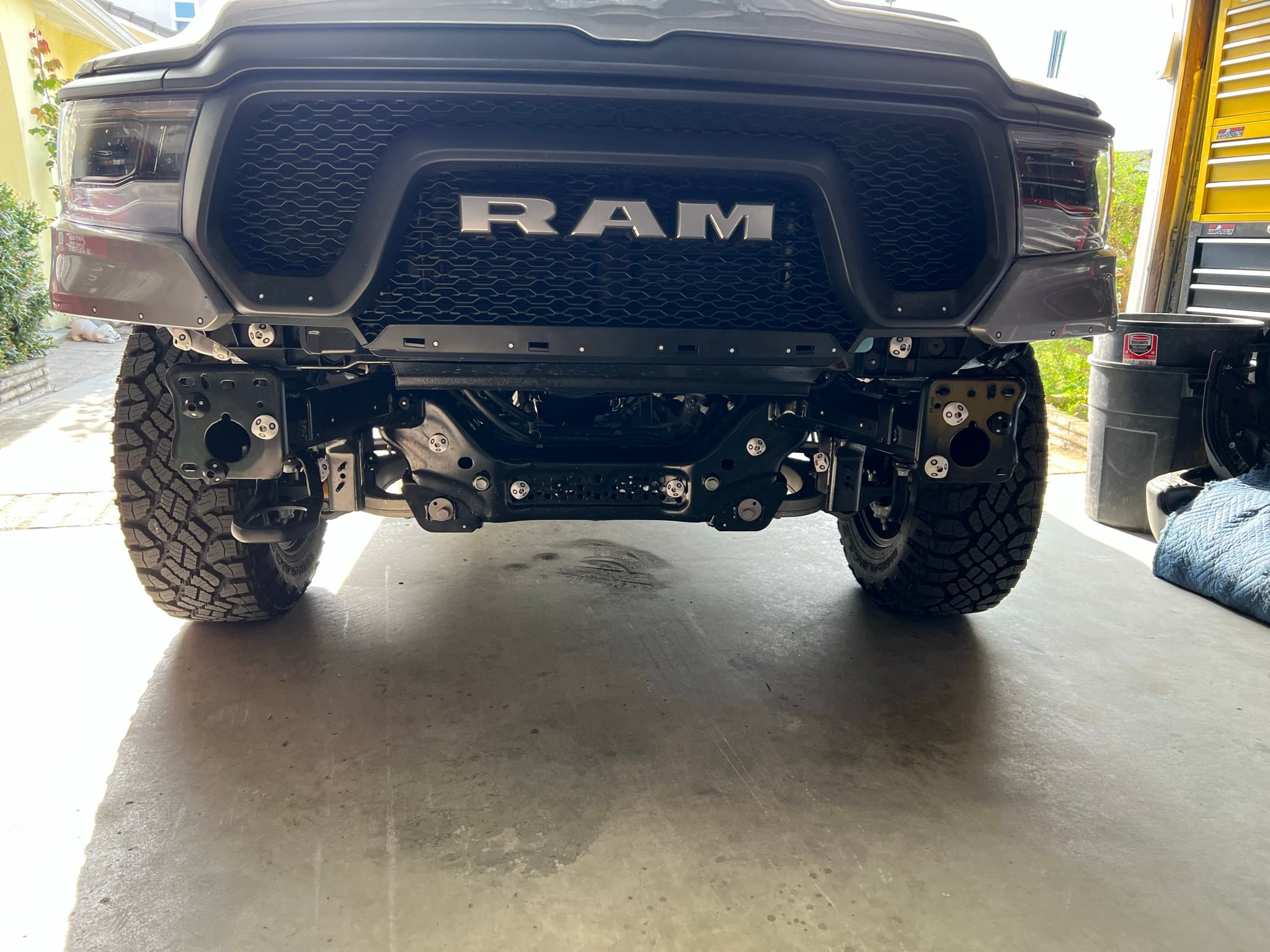
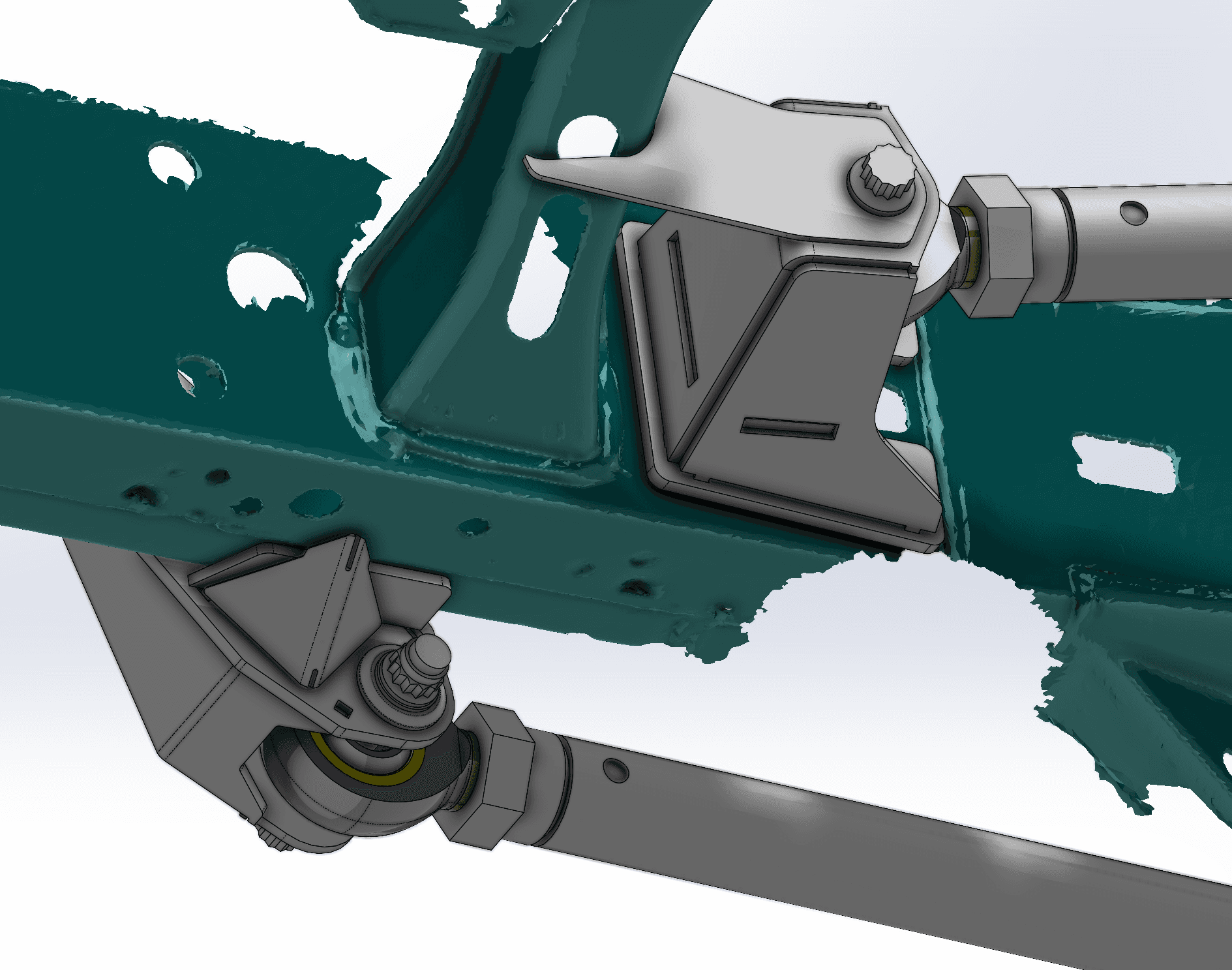
Use as-built when you are designing something to fit the real object. A bumper has to bolt to the frame horns that are actually on the truck, not the ones in a factory drawing. Use design intent when you are making replacement or production parts. If a part is worn, you don't want to copy the wear into every new one.
Many jobs need both: a design-intent model, plus a deviation check that shows how far the real part sits from it.
Output formats
| Format | Type | Use it when |
|---|---|---|
| STL | Mesh | 3D printing, reference geometry in CAD, almost any software |
| OBJ, PLY | Mesh | You also want color data, or your software prefers them |
| STEP | Solid CAD | The default for sharing solids between CAD systems and vendors |
| Parasolid (X_T) | Solid CAD | Clean transfer into SolidWorks and other Parasolid-based systems |
| IGES | Surface or solid CAD | A downstream system specifically asks for it |
One thing to know: neutral formats like STEP carry the geometry but not the feature tree. If your team needs to keep editing the model, tell us which CAD system you use before modeling starts.
When you need full CAD vs. a mesh only
A mesh is often enough when you are designing around the scanned object rather than recreating it. SolidWorks and most other CAD tools can bring a mesh in as reference geometry for fit checks, clearance and packaging. A mesh also works for 3D printing a copy, visualization, archiving and comparing a part against its CAD model.
You need full CAD when you are machining or fabricating the scanned part itself, changing its design, producing drawings with tolerances, or sending it to a vendor who requires STEP.
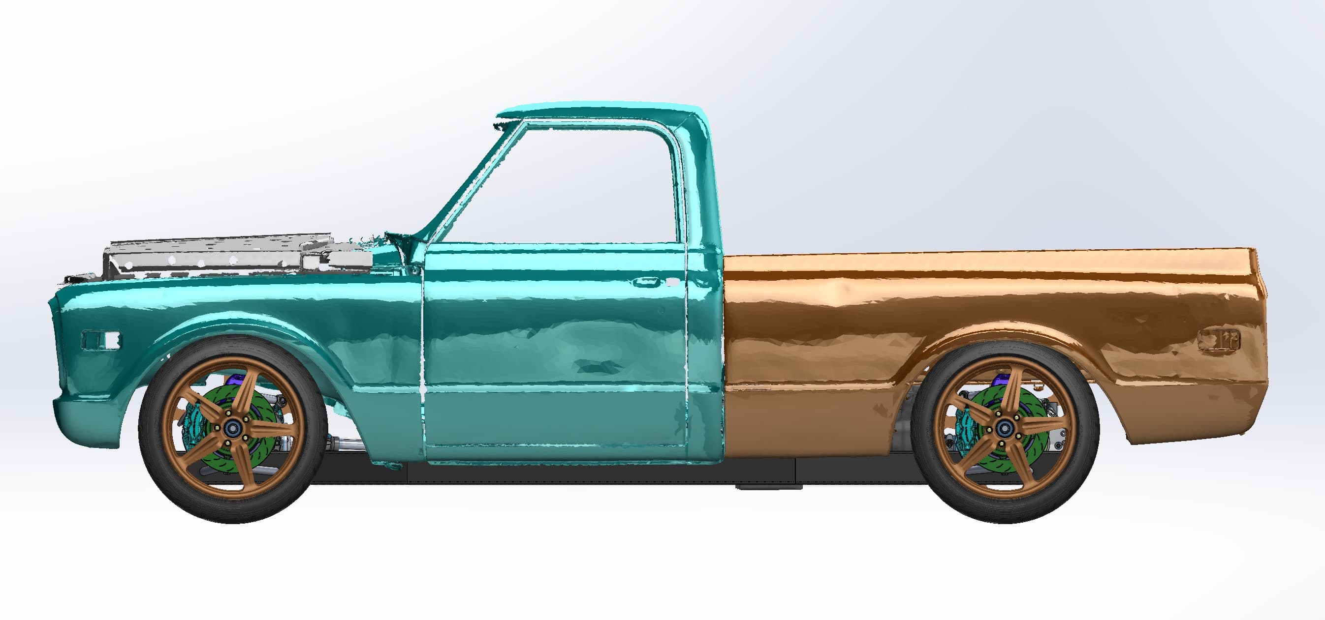
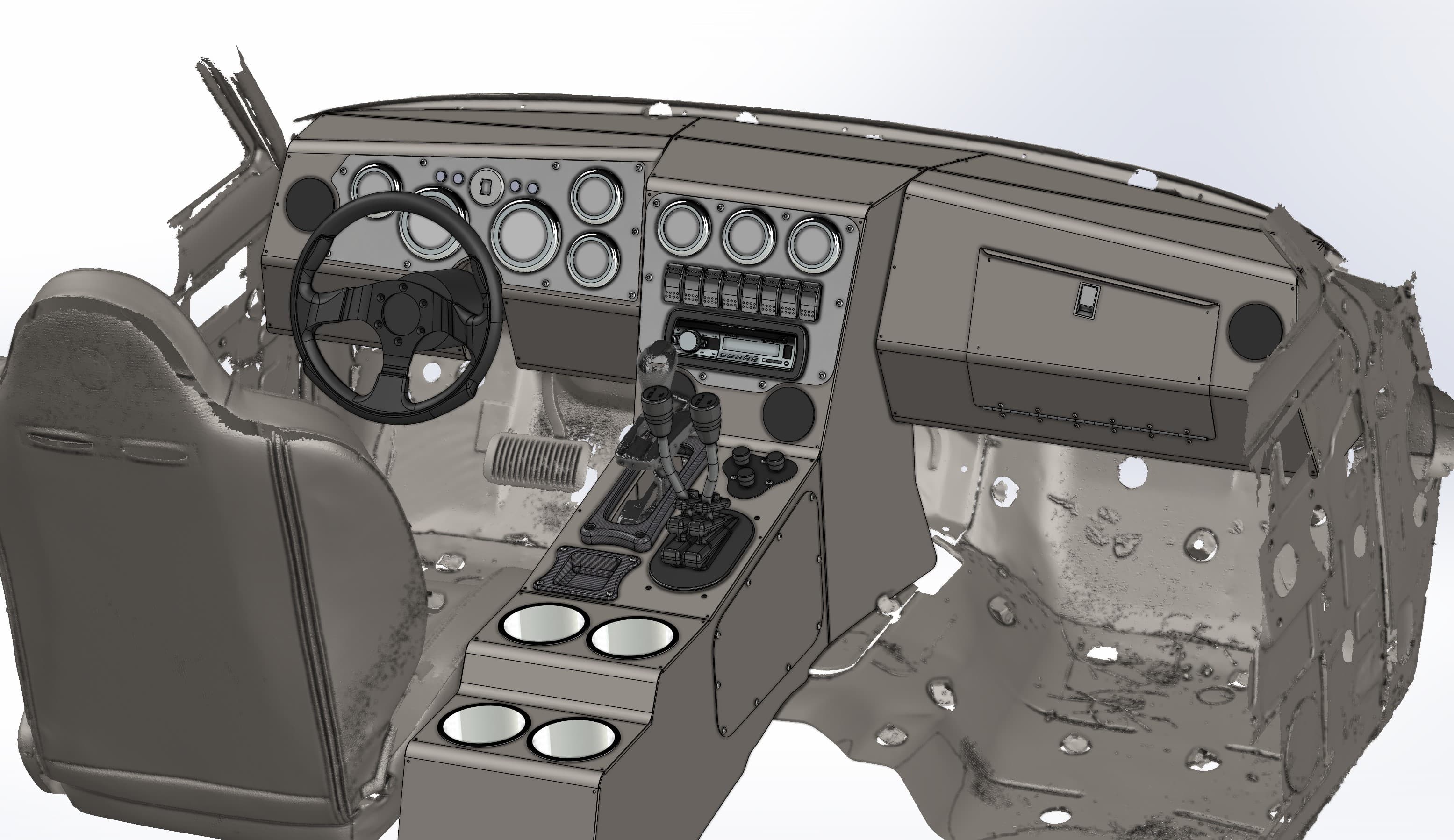
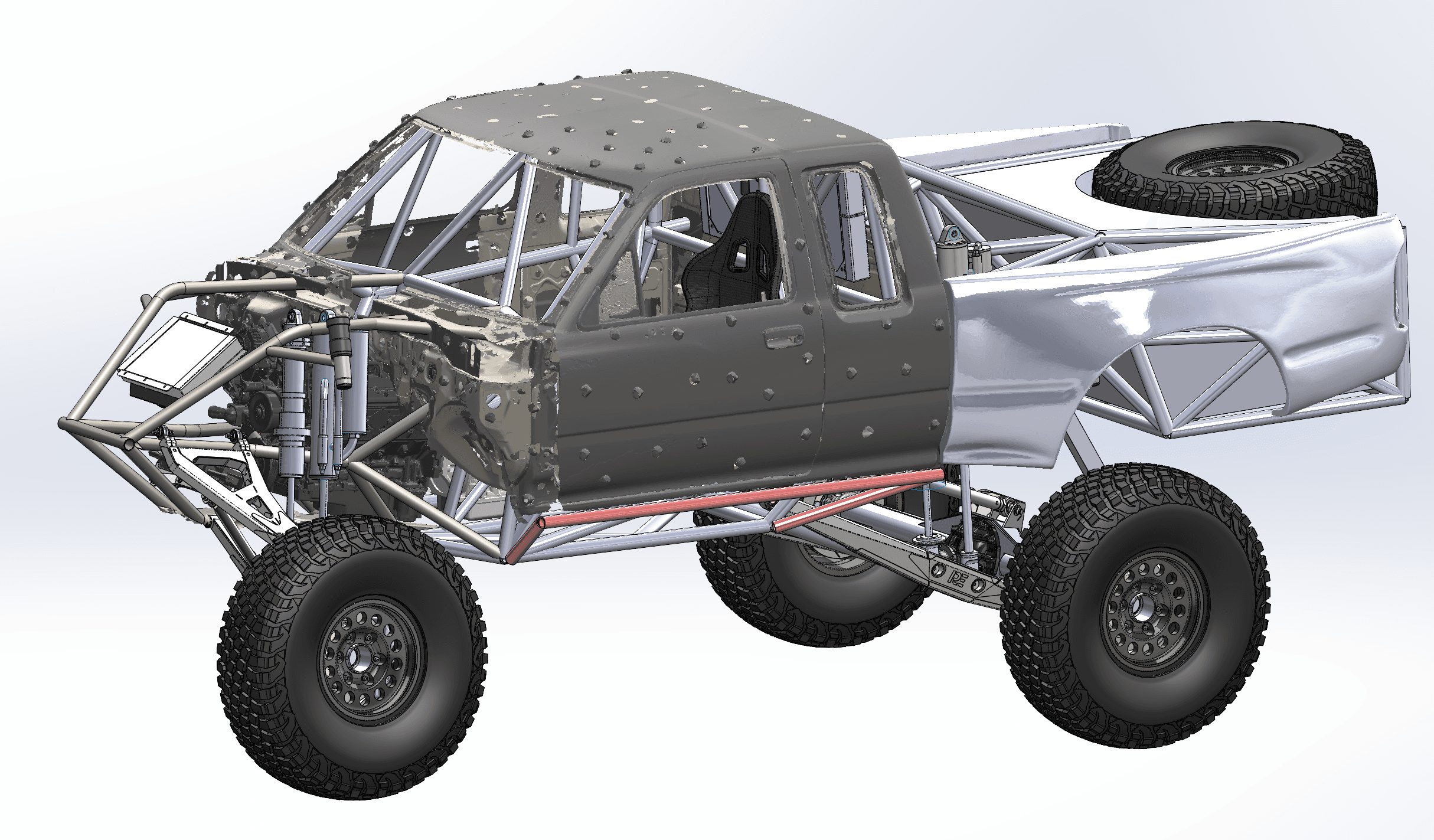
The middle ground is the most common in our shop: keep the scan as a mesh and model only the features your new parts touch. On our trophy-truck chassis design, the scanned cab stays a mesh while the tube chassis, cage and suspension around it are full CAD. The custom dash for a vintage 4x4 on this page's cover worked the same way: the dash and console were designed directly inside the scanned cab.
What to send to start a scan-to-CAD job
To get an accurate quote and the right model, send:
- Photos of the part and its overall size
- What the model is for, and which features are critical
- Whether you need as-built, design intent or both
- The CAD system your team uses
- Any drawings, specs or CAD of mating parts
For a number based on your part, try the instant estimate tool.