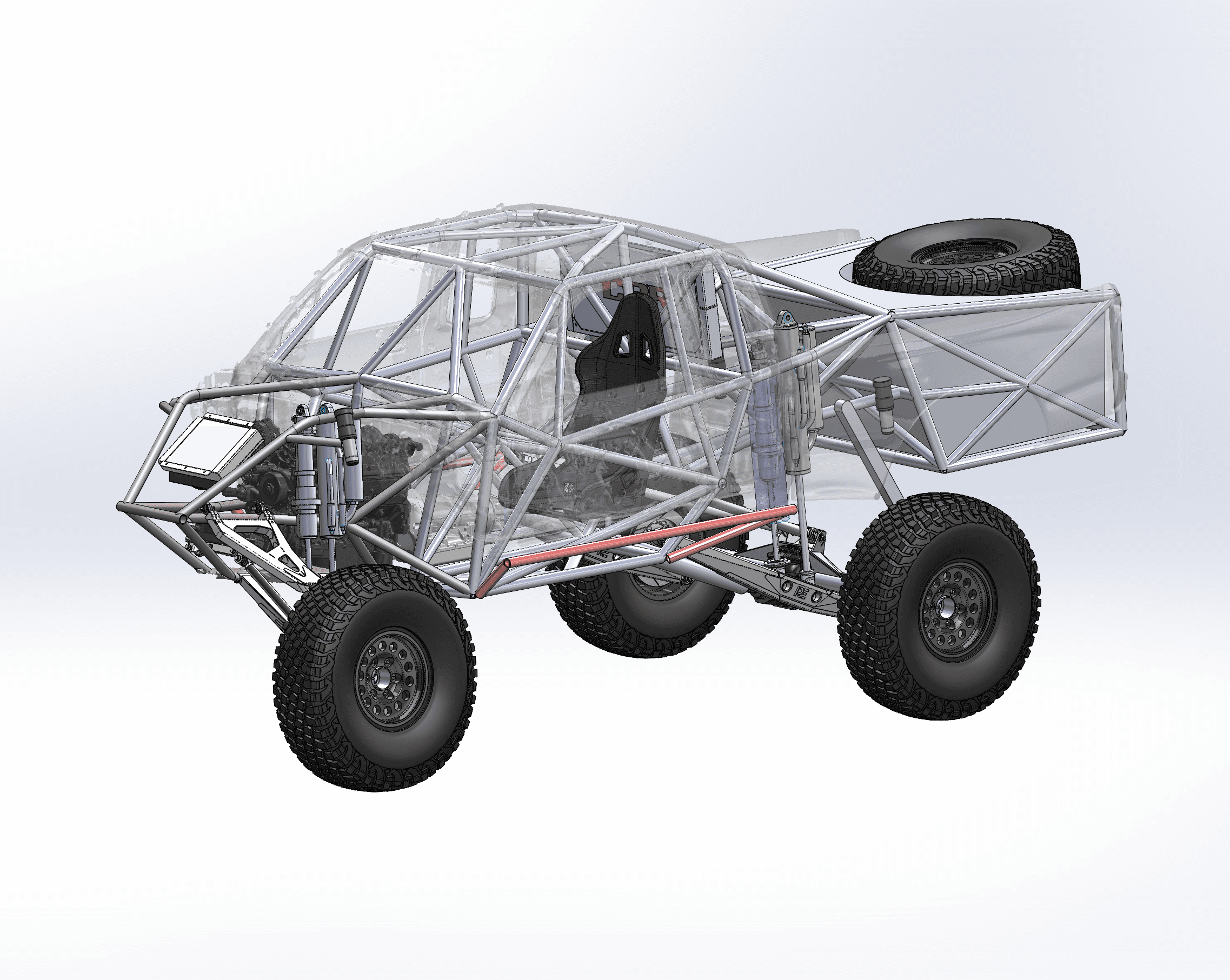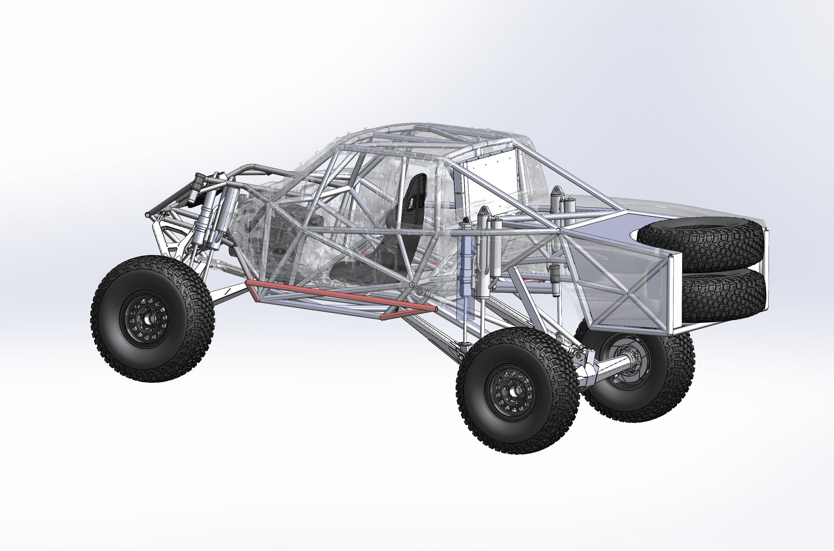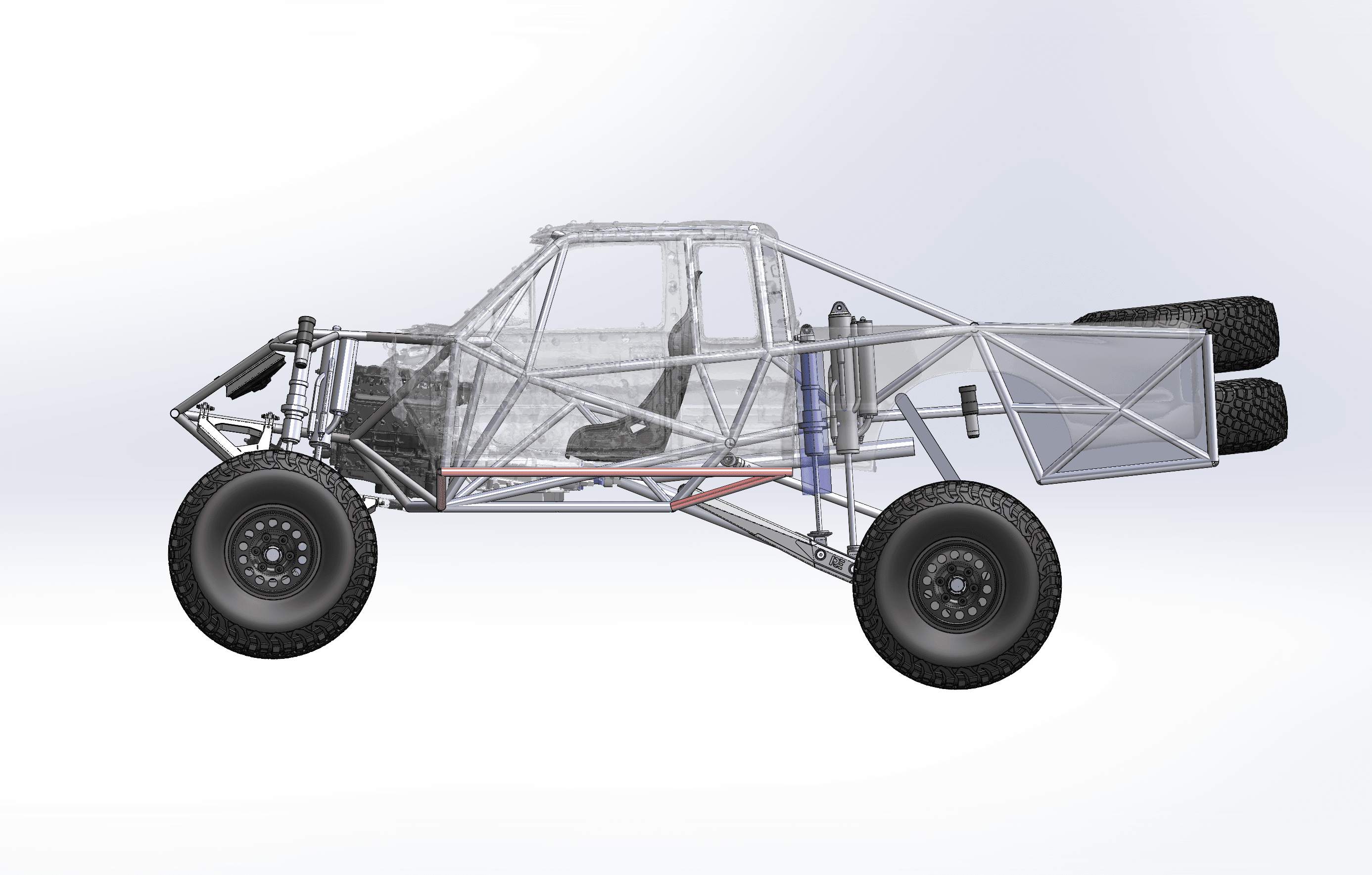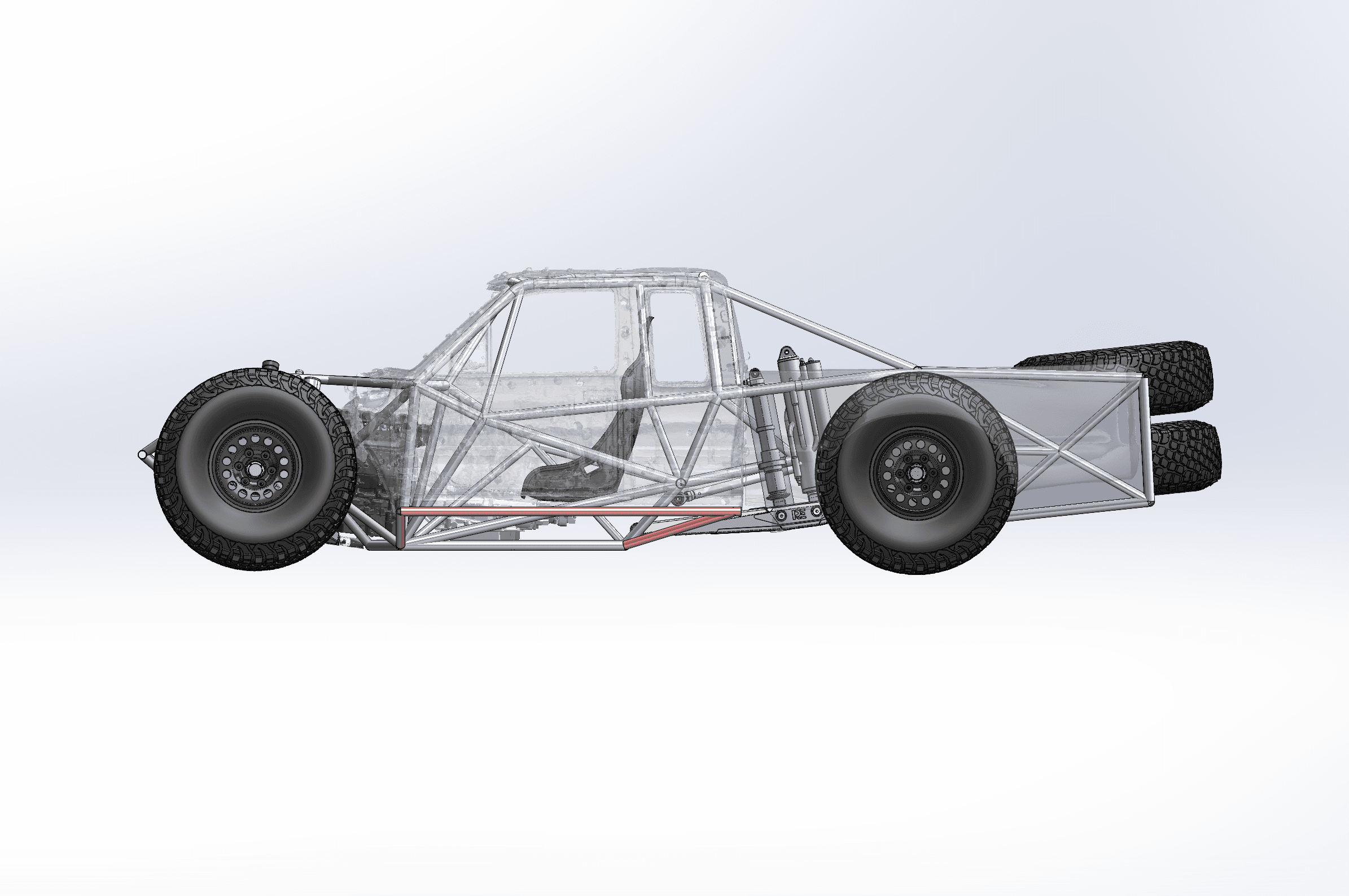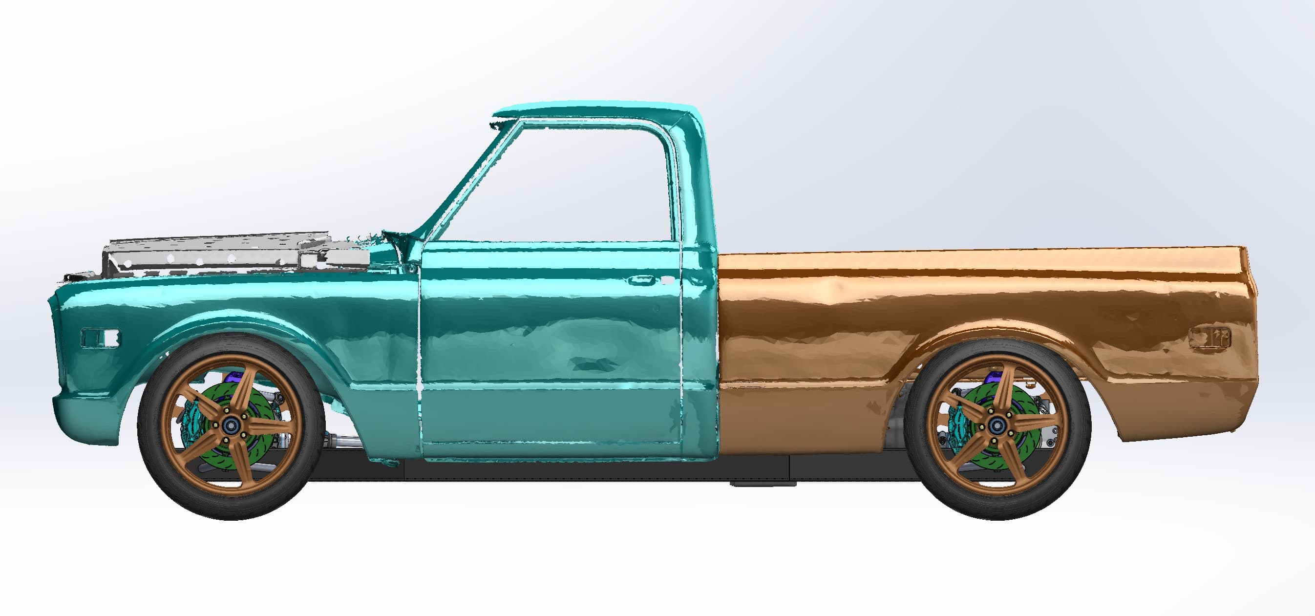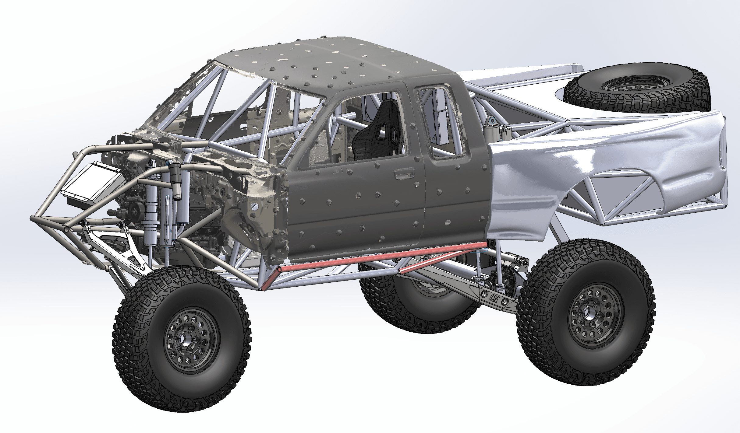
A trophy truck is a race chassis wearing a production cab. The cage, seats, shocks and long-travel suspension all have to package around sheet metal that was never designed for them. For this trophy-truck chassis design, we 3D scanned an extra-cab pickup cab and front clip, then built the full tube chassis, roll cage and suspension in CAD around the scan. The cab stayed a mesh in the assembly, scan-target dots and all, and became the reference the chassis was laid out against.
Why scan the cab first
A production cab is a pile of compound curves: roof line, A-pillars, door openings, floor and firewall. Cage tubes have to pass close to all of them, the seat has to sit in the right place, and the front suspension and engine have to clear the front clip. Measuring that by hand means guessing at curves and finding the misses later with a grinder.
A 3D scan replaces the guesswork with the real shape of the cab. Every tube in the CAD model can be checked against the body before anyone bends steel. We've designed trophy trucks and high-performance off-road vehicles, and on a cage that has to run close to the body, the scan is where we start.
Keeping the cab as a mesh
In the design renders, the cab is still the scan mesh. It wasn't rebuilt as solid CAD surfaces, because it didn't need to be: the chassis only has to know where the cab is. The mesh went into the assembly as a reference, and only the new parts were modeled. Skipping the surfacing step saves time that adds nothing to the build. Our post on STL vs STEP scan deliverables explains when a mesh is enough and when you need full CAD.
Designing the chassis and suspension
Around the scanned cab, the design adds:
- A front tube bumper and radiator mount
- Long-travel front A-arms with bypass shocks
- A full roll cage with a race seat placed inside the scanned cab
- Rear trailing arms with bypass and coilover shocks
- A rear tire carrier holding twin spares
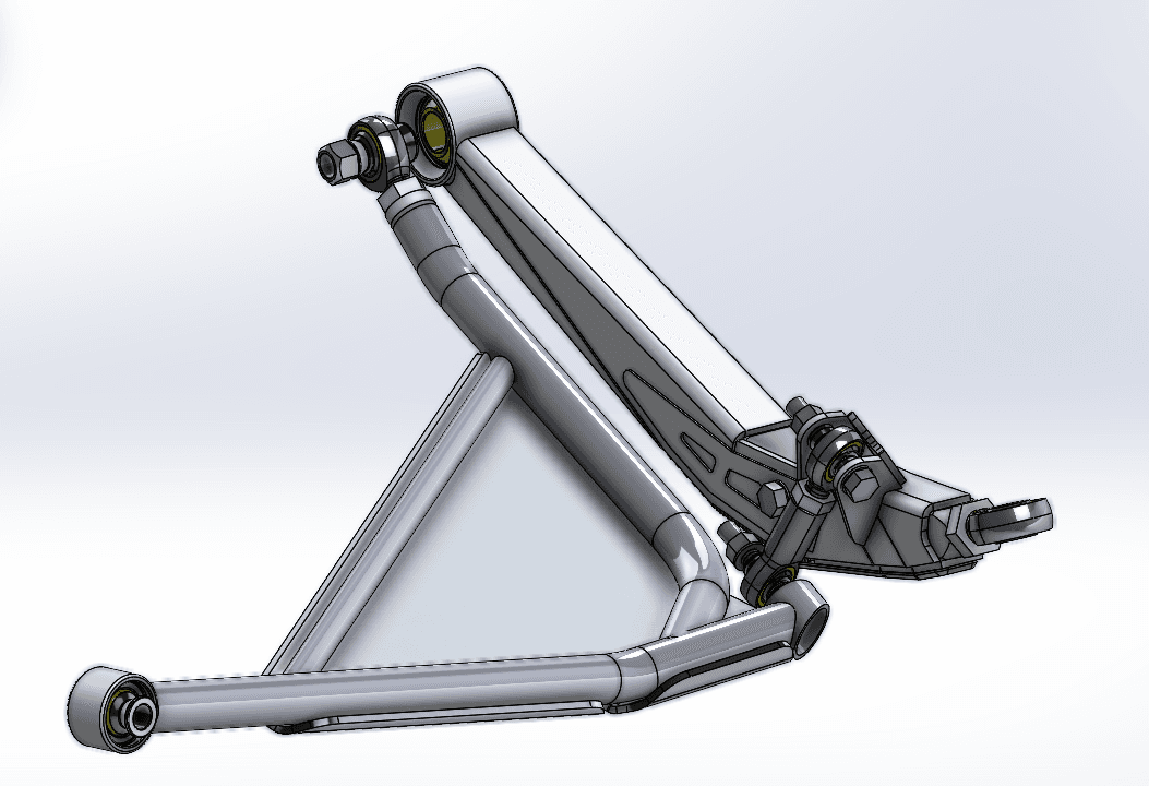
The design set also includes a fabricated suspension arm: a boxed plate arm with a large pivot bushing, a triangulated tubular A-frame with a gusset and skid plate, and heim joints at the ends. It's in the gallery below.
Checking travel: droop, ride height and full bump
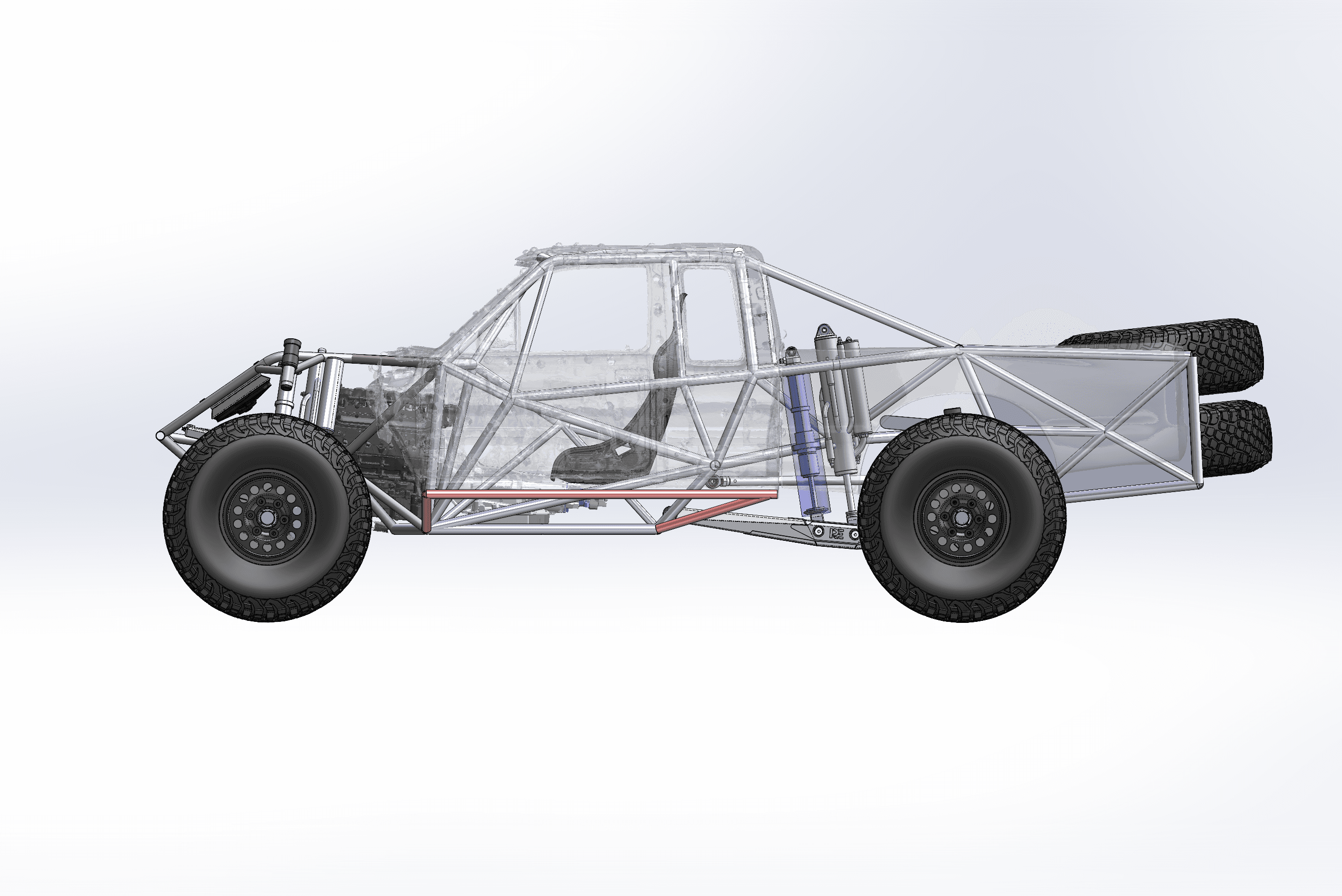
Long travel is the point of a trophy truck, so the suspension was posed at three positions: extended toward droop, at ride height and compressed to full bump. At full bump the tires tuck up into the chassis, which is exactly where a tire-to-cage or shock-to-body hit would show up. With the scanned cab in the model, those checks happen on screen instead of on the first test drive.
What came out of it
- A scan mesh of the extra-cab pickup cab and front clip
- A trophy-truck chassis and cage model built in SolidWorks around that mesh
- The suspension posed at droop, ride height and full bump
- Renders for design review and sign-off
Building a race truck around a stock cab?
The same workflow fits prerunners, desert race trucks, UTV cages and any build where a tube chassis meets a factory body. Scan the cab, keep it as a mesh, and design the chassis around the real thing. See how we work with race teams on the motorsports industry page, read about our reverse engineering and scan-to-CAD service, or get an instant estimate for scanning your cab or chassis.