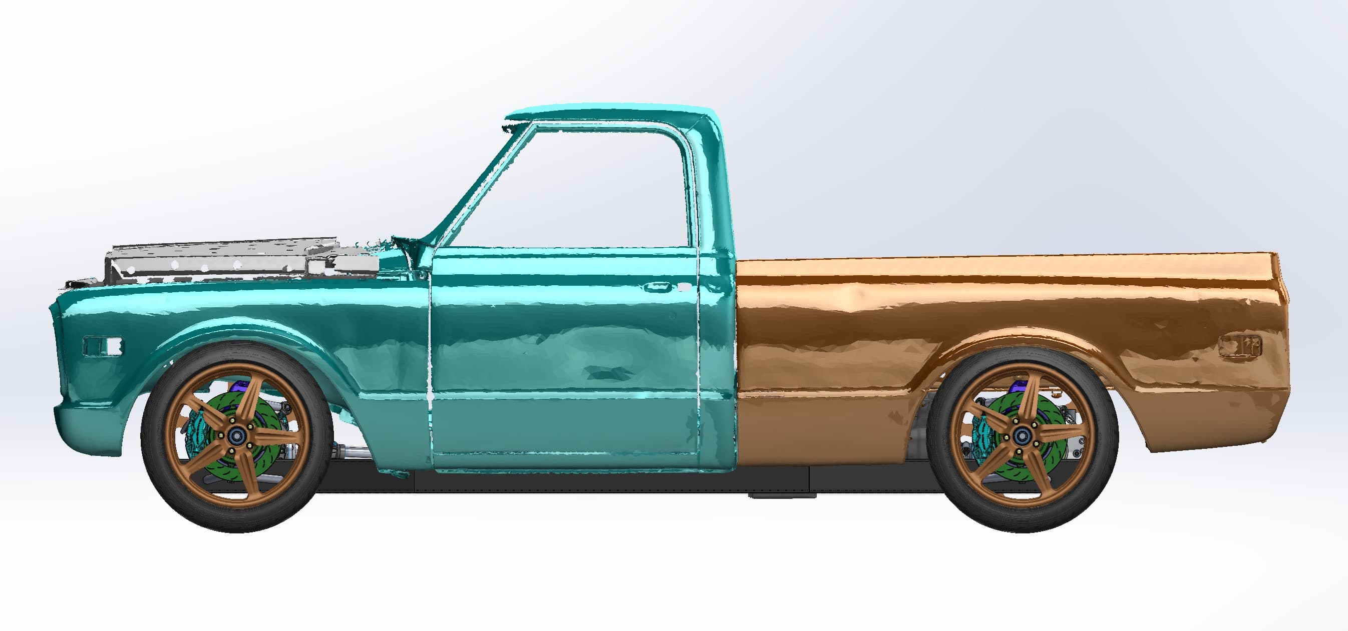
Putting a big-block V8 behind the cab of a '67–72 Chevy C10 and driving all four wheels is a packaging problem long before it's a fabrication problem. Every hardpoint has to fit inside a body that left the factory more than 50 years ago, and no drawing will tell you exactly how this particular truck's sheet metal sits today. So we started with a 3D scan of the C10's cab, front clip and bed, then designed a mid-engine, all-wheel-drive chassis in CAD around the real body. This is scan-to-CAD the way custom chassis work should go: measure the body first, then design.
The challenge: a mid-engine layout under a classic body
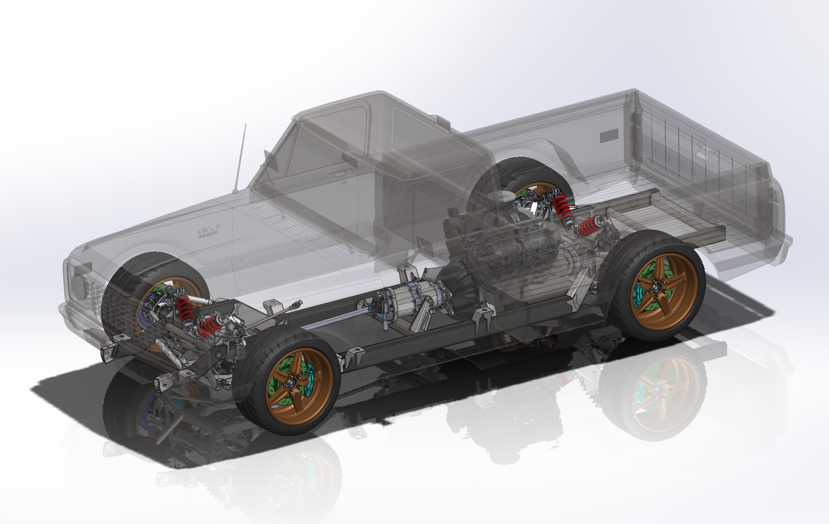
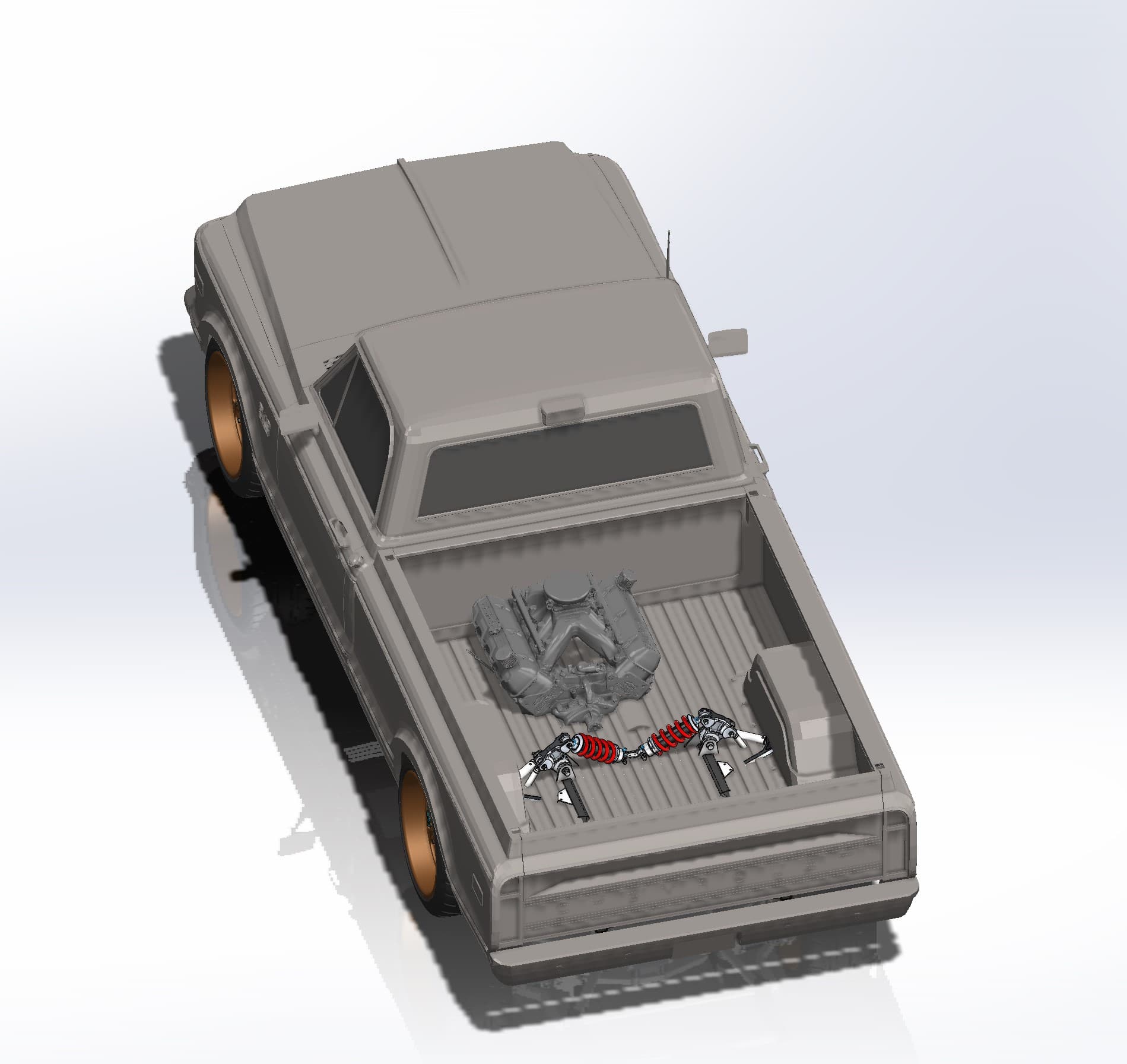
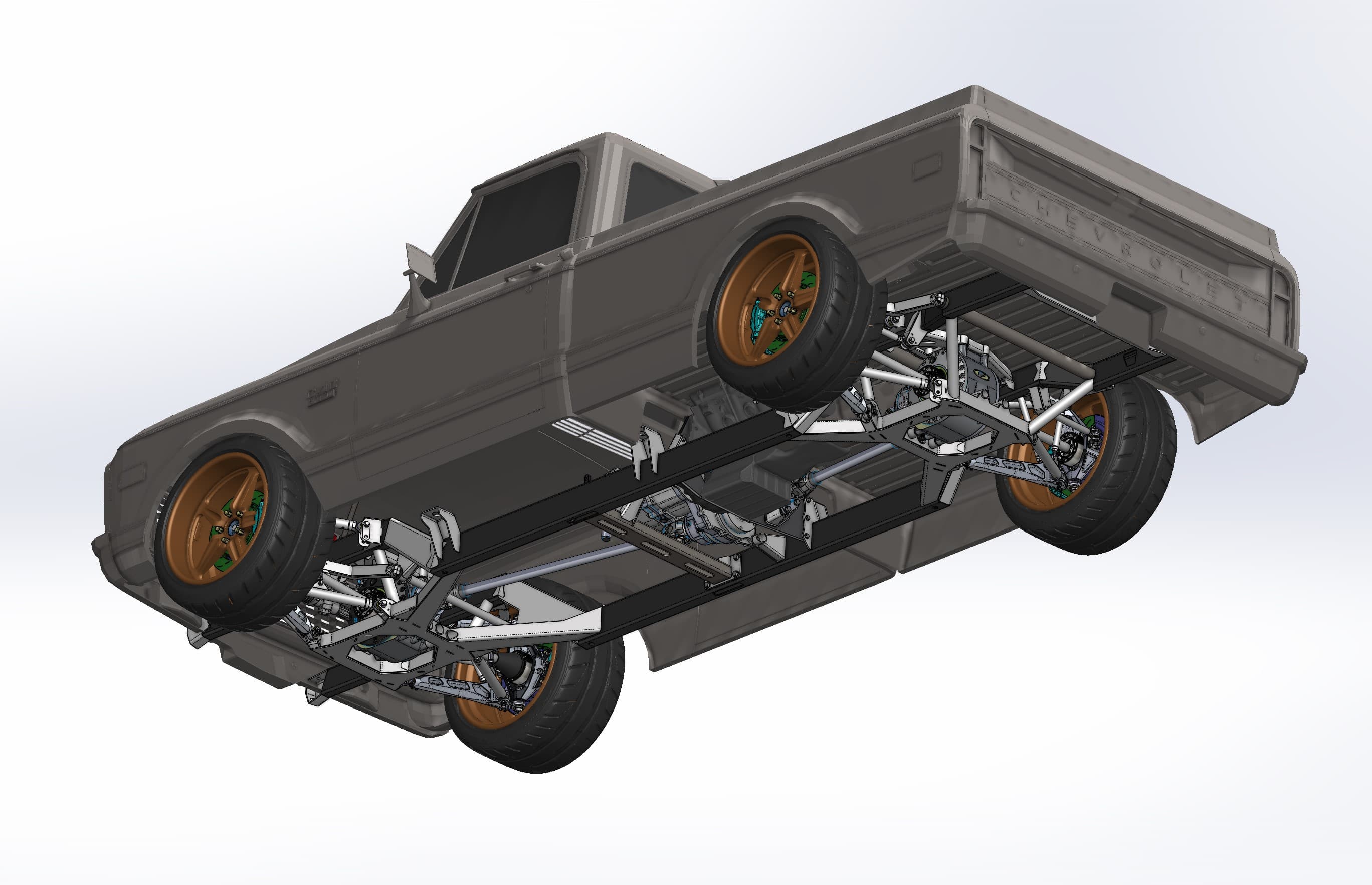
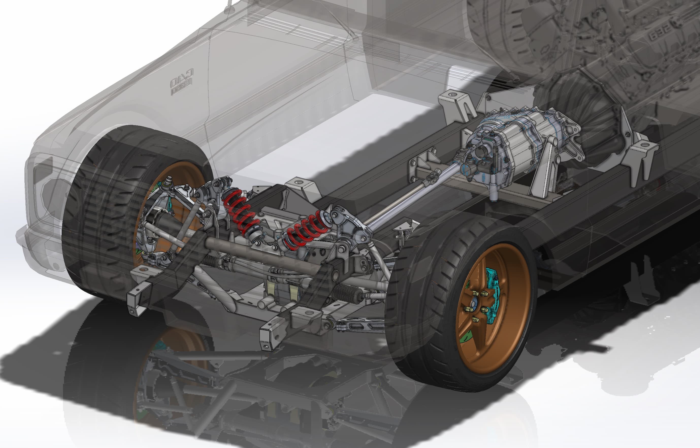
The layout moves almost everything. The engine leaves the engine bay and sits behind the cab, where the bed floor used to be. The transmission and transfer case sit in the middle of the chassis, with a driveshaft running forward to a front differential. Both ends get rocker-actuated inboard coilovers, and the truck sits low on big wheels and brakes tucked under the original fenders.
All of that has to clear a cab floor, firewall, inner fenders, wheel openings and bed sides made of compound curves. Those are slow to measure by hand and easy to get wrong. A scan captures the whole body in one dataset, so every clearance question gets answered in CAD.
Scanning the C10 body
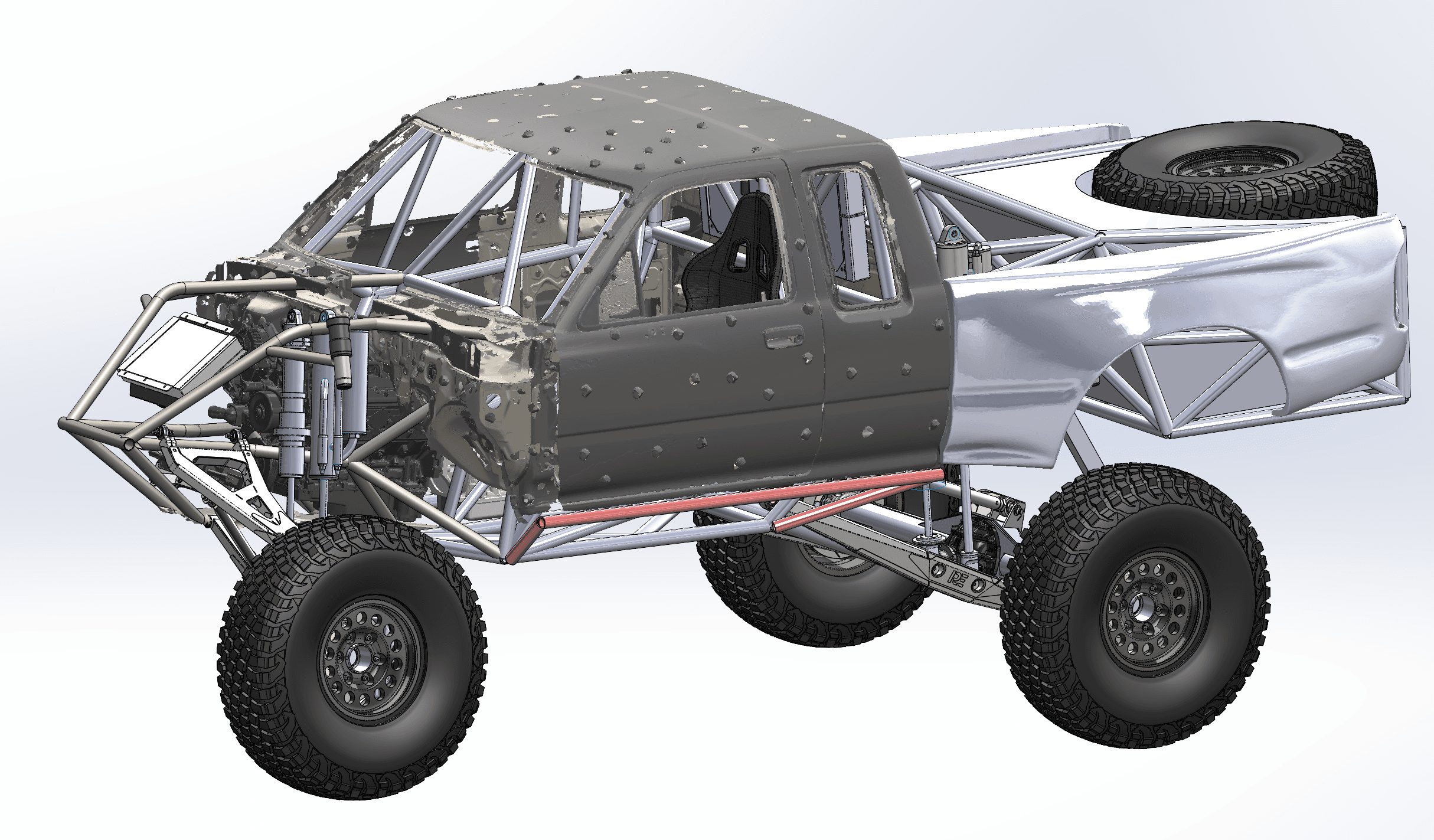
We scanned the body with a handheld 3D scanner and split the mesh by section: the cab and front clip in teal, the bed in copper. Look closely at the hood and you can see small round holes in the mesh. That's where positioning targets sat. The scanner tracks those reflective dots to keep its position as it moves around the truck.
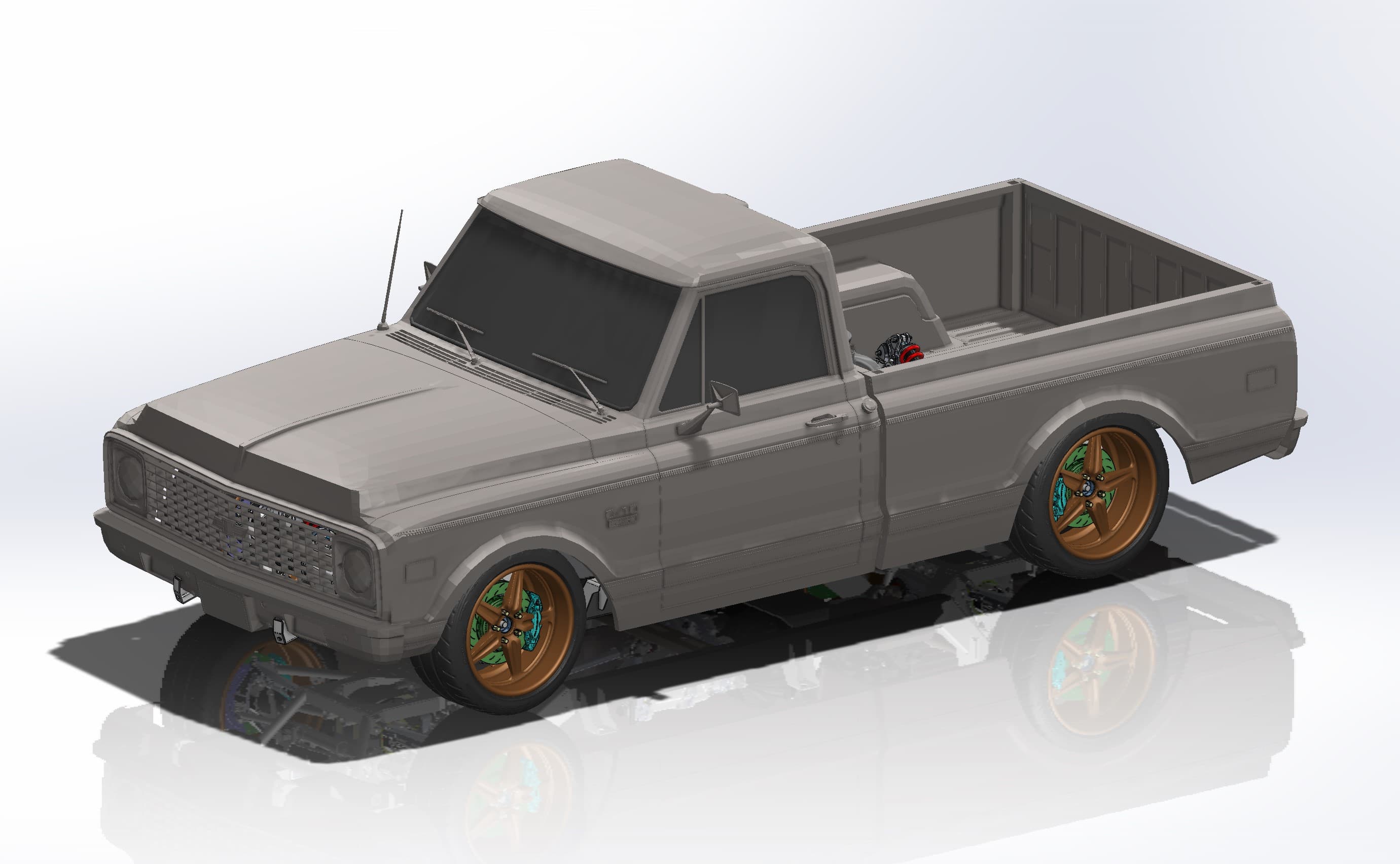
Before any chassis tubes existed, the scanned body went onto CAD wheels and tires, so the stance and wheel fitment could be judged right away.
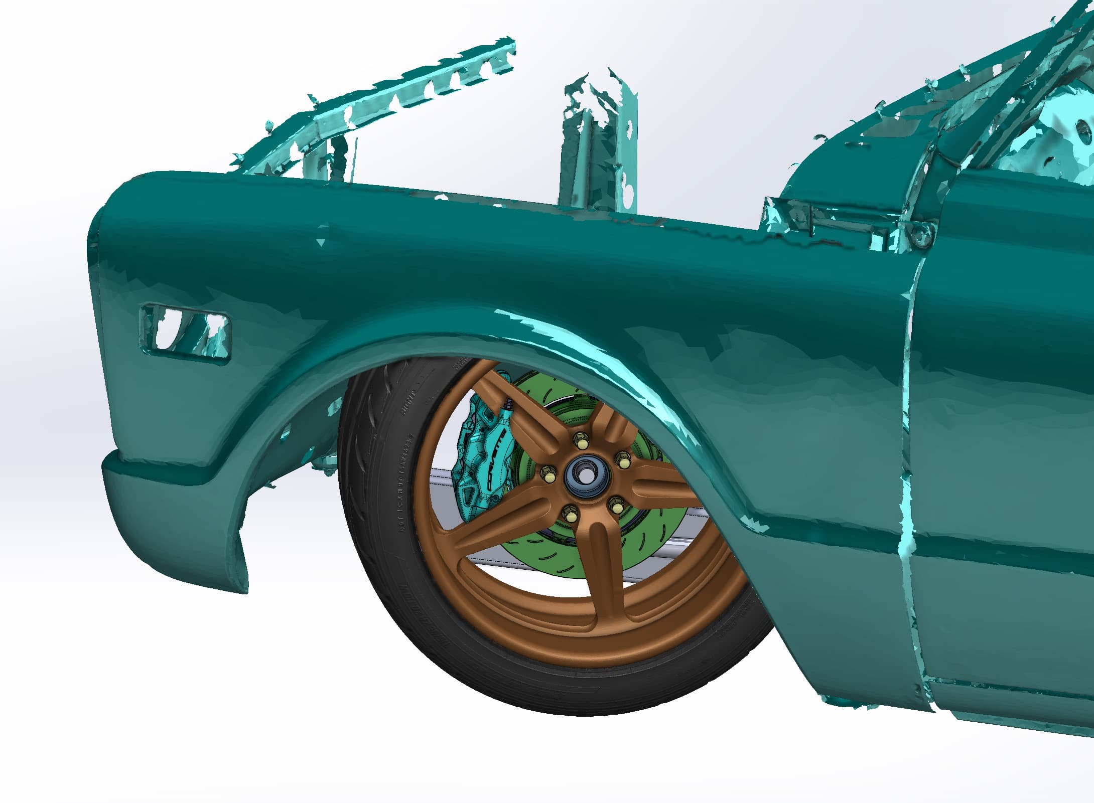
From scan to chassis design
With the body in the assembly, the chassis was designed underneath it: box-section frame rails with fabricated crossmembers, tubular double wishbones, a steering rack, inboard coilovers at both ends and the big-block mounted behind the cab. The scan set the limits. The engine had to clear the cab's back wall and fit between the bed sides. The front suspension had to live inside the firewall and inner fenders. The wheels and brakes had to sit in the arches at the planned ride height.
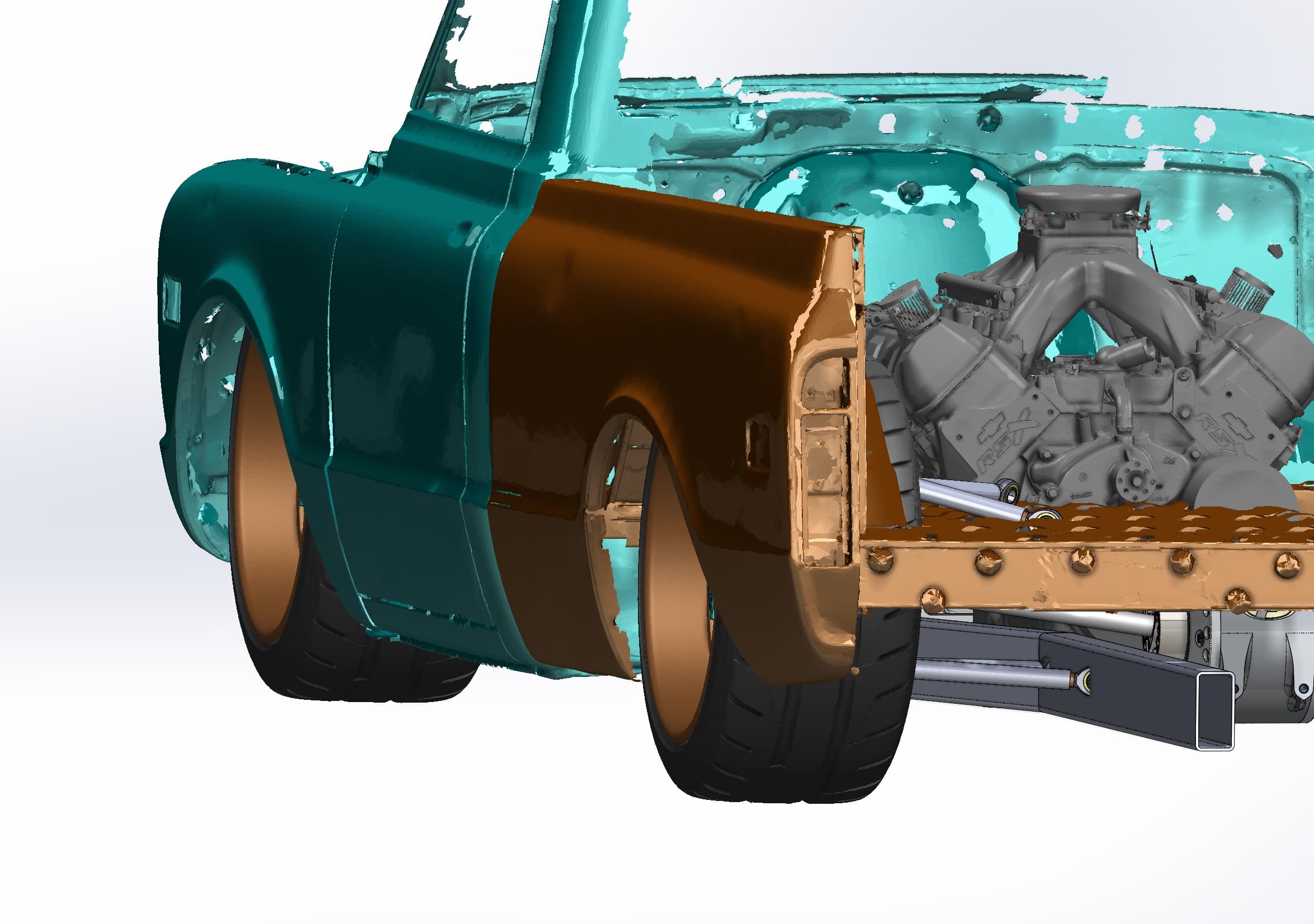
Working this way also makes the X-ray views in the gallery possible. With the body set to transparent, you can see how every chassis hardpoint relates to the shell around it, which is the conversation a builder and an owner need to have before any metal gets cut.
What the customer got
- A scan mesh of the C10 body, split into cab and front clip and bed
- A complete mid-engine, all-wheel-drive chassis model built in SolidWorks
- Engine, wheel and brake packaging checked against the scanned body
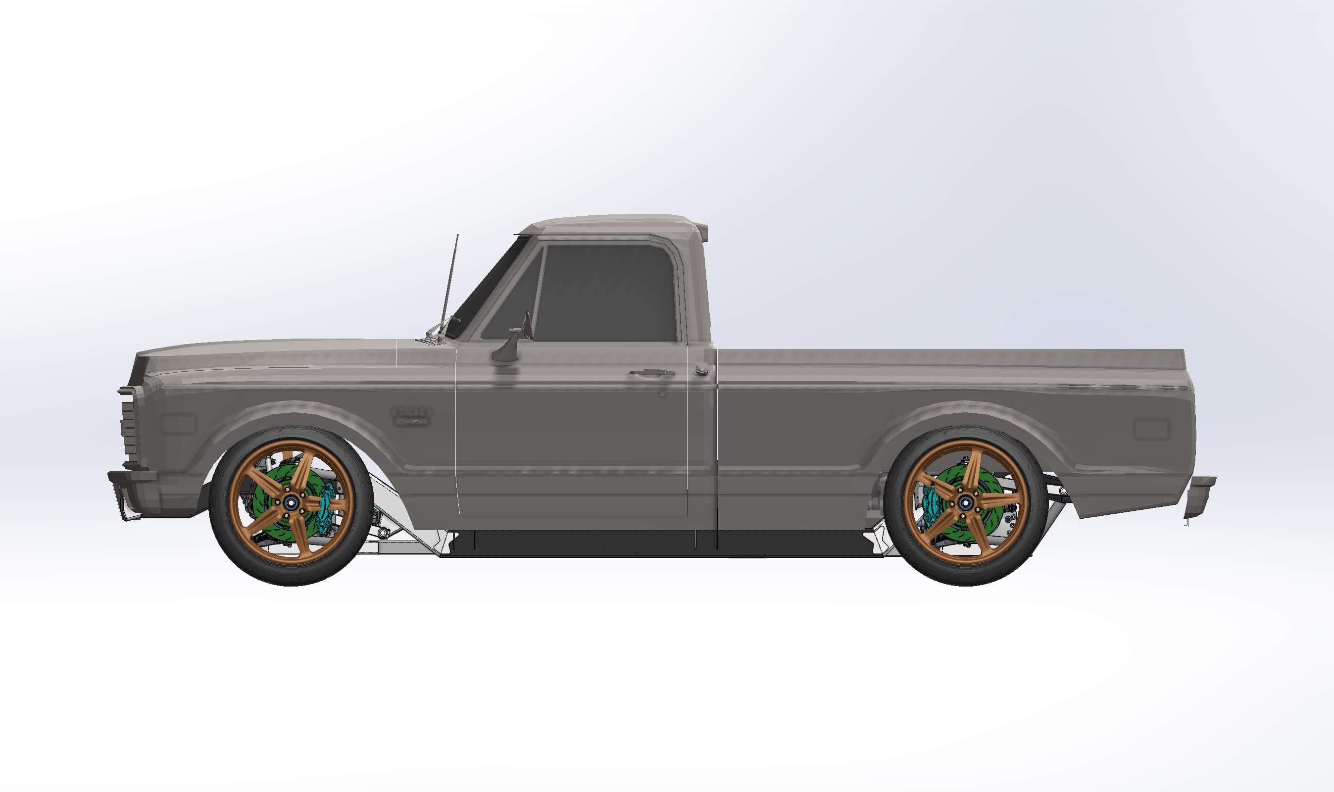
- Renders for review, from X-ray layouts to a finished side profile
Why scan before you design a custom chassis
Restomods, pro-touring builds, engine swaps and full custom chassis all have the same problem: new parts have to fit an old body. A scan gives you the body as it actually is, so the chassis is designed to the truck in your shop, not to a catalog drawing or a tape measure.
If you're planning a build like this, our reverse engineering and scan-to-CAD service covers the scan and the design, and the scan-to-CAD guide explains how a mesh becomes usable CAD. You get the scan as an STL mesh and CAD as STEP, Parasolid (X_T) or IGES if your team designs in-house. See more automotive 3D scanning work, or get an instant estimate for scanning your body or chassis.