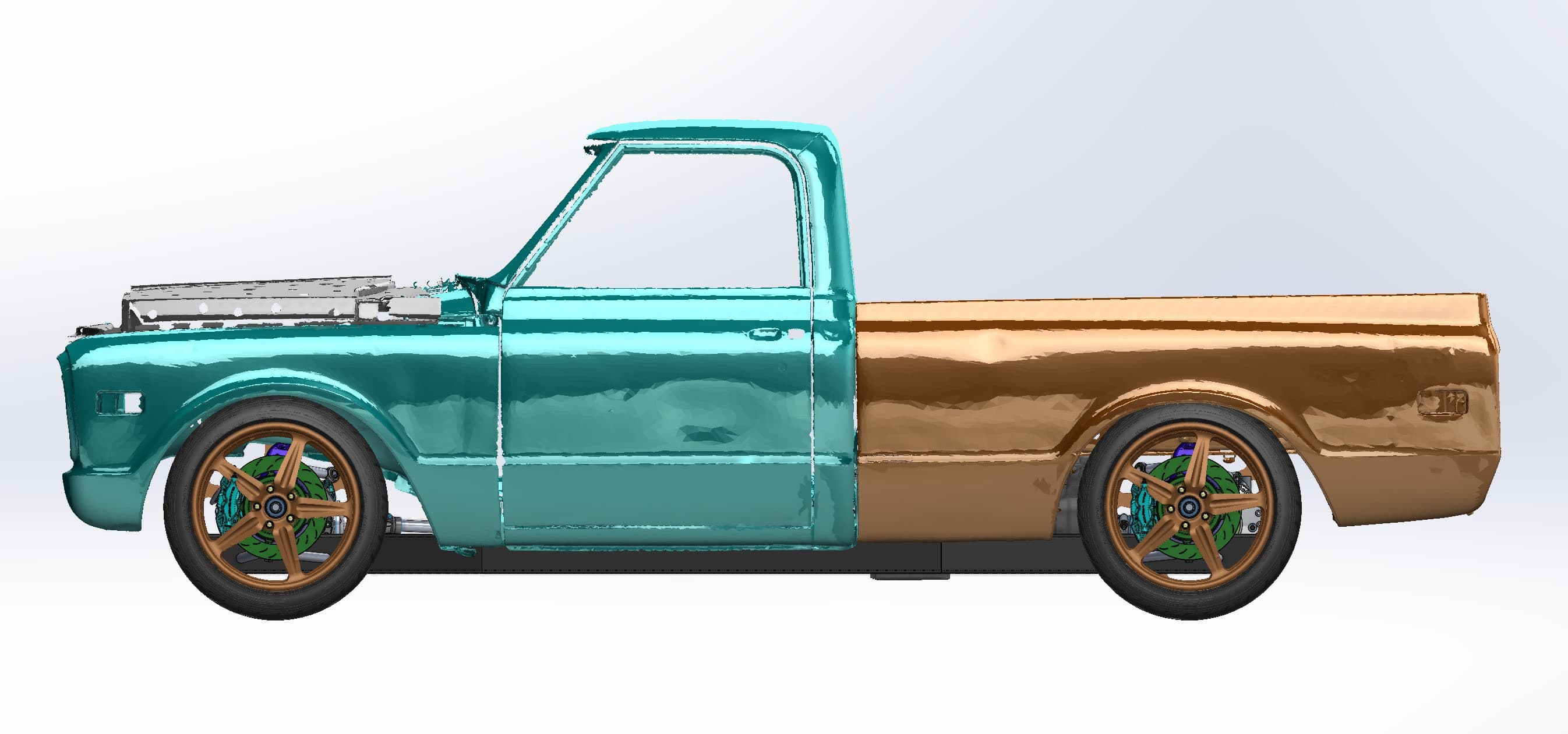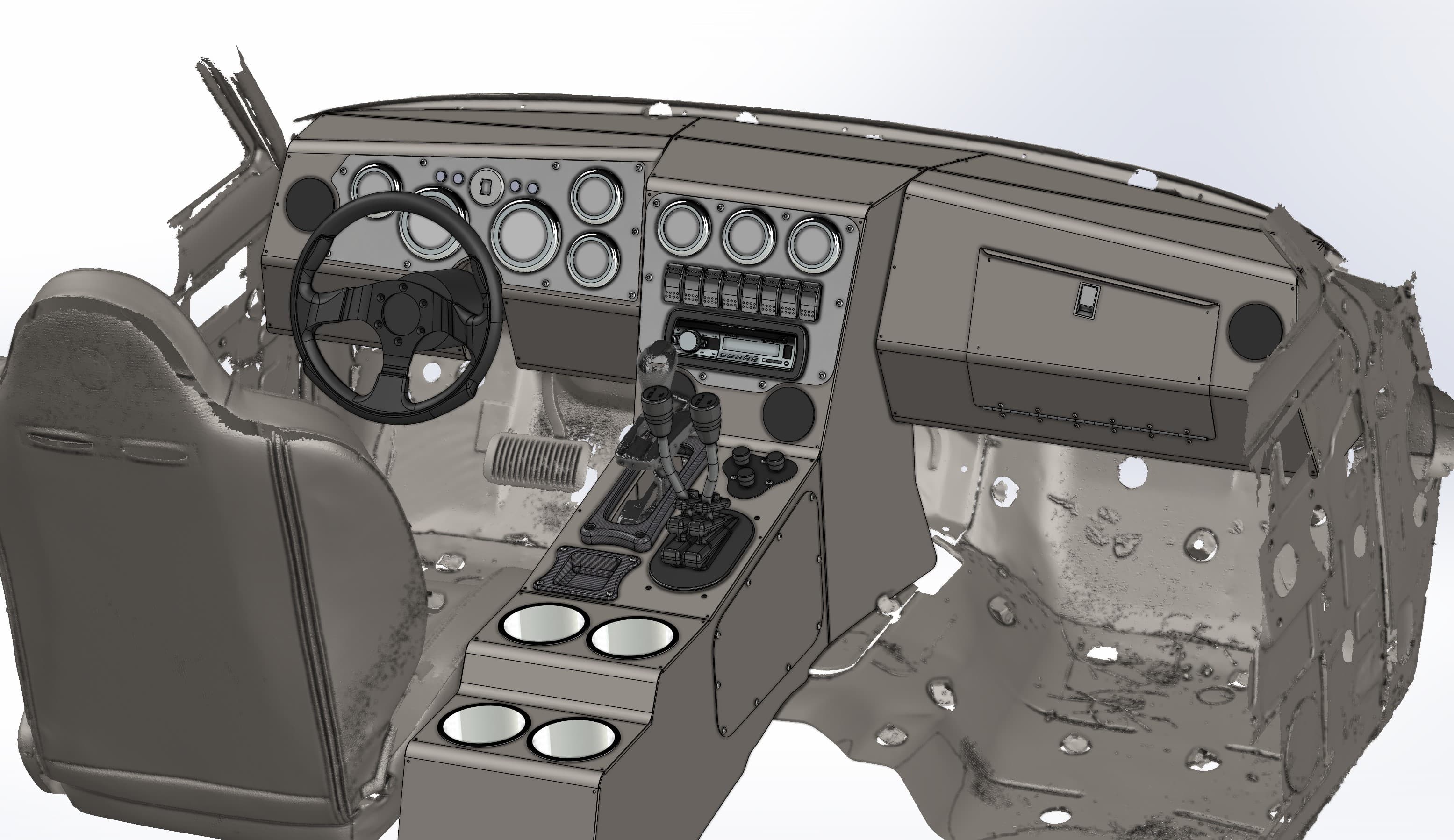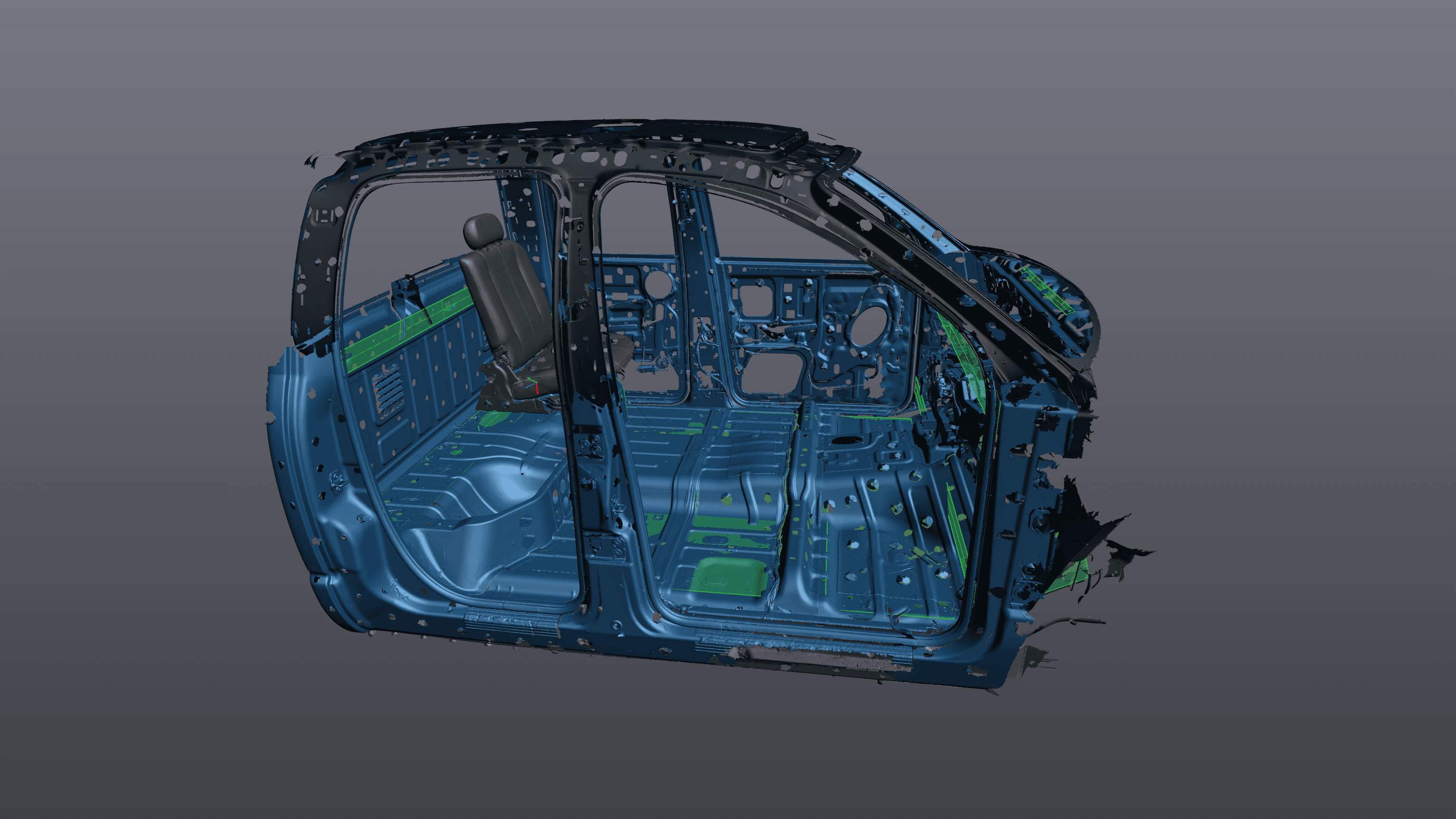
A 3D scan gives you a mesh first: a surface made of thousands to millions of small triangles. STL is the most common mesh format. STEP is a CAD format that describes solids and surfaces with exact geometry (planes, cylinders, curved surfaces) that CAD software can edit and machine shops and toolmakers can work from. So STL vs. STEP comes down to what you'll do with the file. To look at it, 3D print it or check fit and clearance, a mesh is usually enough. To machine it, cut it from sheet, mold it or change the design, you need CAD.
Many scan jobs deliver both, and many need something in between. Here's what each format is, a side-by-side comparison, a decision guide by end use, and what "key features only" CAD means.
Mesh formats: STL, OBJ and PLY
Every 3D laser scanning job starts as a mesh. The scanner captures points on the surface, and processing turns them into connected triangles. A mesh describes shape very well, including wear, dents and casting texture, but it has no idea what a feature is. A drilled hole is just a ring of triangles. There's no diameter to edit and no axis to mate to.
- STL stores triangles and nothing else: no color and no units. The software opening it has to assume millimeters or inches, which is how a part shows up 25.4 times too big or too small. Every 3D printing slicer reads it.
- OBJ stores polygons and can reference material and texture files, so it can carry color. It's common in visualization and rendering.
- PLY can store color and other values for each point. It's common for raw and processed scan data.
Meshes are the right deliverable for visualization, 3D printing, packaging and clearance checks, archiving an as-built shape, and as the measured data in an inspection. Most CAD systems, SolidWorks included, can import a mesh as a reference body you design around.
CAD formats: STEP, Parasolid and IGES
CAD formats describe a solid model as a B-rep (boundary representation): faces bounded by edges, where each face is an exact surface. A hole is a cylinder with a diameter and an axis. A flange face is a true plane. Units are stored in the file. Getting from a scan to a solid like this is modeling work, which is what reverse engineering means.
- STEP (ISO 10303) is the neutral standard. Nearly every CAD and CAM system opens it, so it's usually the first choice.
- Parasolid (X_T) is the native format of the Parasolid modeling kernel used by SolidWorks, Solid Edge, NX and Onshape. Use it for the cleanest transfer into those systems.
- IGES is an older neutral format that's strong on surfaces and weaker on solids. Imports sometimes arrive as loose surfaces that need knitting together. Use it when a legacy CAM or tooling system asks for it.
None of these formats carry the feature tree. You get finished geometry, which most CAD systems can edit directly (move a face, resize a hole) or rebuild features from.
STL vs. STEP side by side
| Mesh (STL, OBJ, PLY) | CAD (STEP, X_T, IGES) | |
|---|---|---|
| What's in the file | Thousands to millions of triangles | Solids and surfaces defined by exact geometry |
| Holes, planes, bosses | Only triangles in that shape | Real cylinders, planes and edges |
| Editing | Limited: trim, smooth, patch | Change dimensions, add and remove features |
| Units | Not stored; the software assumes | Stored in the file |
| Detail | Everything the scanner saw, including wear and texture | Modeled shape, built to the scan |
| How it's made from a scan | Processing the scan data | Modeling in CAD (reverse engineering) |
| Best for | Visualization, 3D printing, clearance checks, inspection data | CNC machining, sheet metal, molds, drawings, design changes |
| Opens in | Slicers, viewers, inspection software, CAD as a reference | Any CAD or CAM system |
Which do I need? Decide by end use
3D printing: mesh
A slicer only needs a clean, closed STL. You need CAD first only if you want to change the part before printing it.
Visualization, renders and archives: mesh
Use OBJ or PLY when color data is part of the scan, STL when it isn't. A mesh is also the best record of a part as it exists today.
Packaging, fit and clearance checks: mesh, often plus key features
Import the mesh into your CAD and design around it. If you need to mate new parts to it, add key features (below) so you aren't snapping to triangles.
Inspection against a design: mesh plus your CAD
The scan mesh is the measured data and your STEP model is the nominal. Dimensional inspection compares the two and shows the deviation as a color map.
CNC machining: CAD
Machine shops want STEP or Parasolid. CAM needs real faces and edges for pockets, drilling cycles and contours. Some CAM software can surface-machine a freeform mesh, but there's no true hole to drill or flat face to finish, so prismatic features suffer.
Sheet metal, laser and waterjet parts: CAD
Flat patterns come from a sheet metal CAD model with real bends and thickness. A mesh can't be unfolded.
Injection molding, casting and composite tooling: CAD
Toolmakers work from STEP or Parasolid solids they can add draft, parting lines and shrinkage allowance to.
Design changes and drawings: full CAD
If the part will be modified, re-toleranced or drawn, you need a fully modeled part with clean features.
Key features only: the middle option
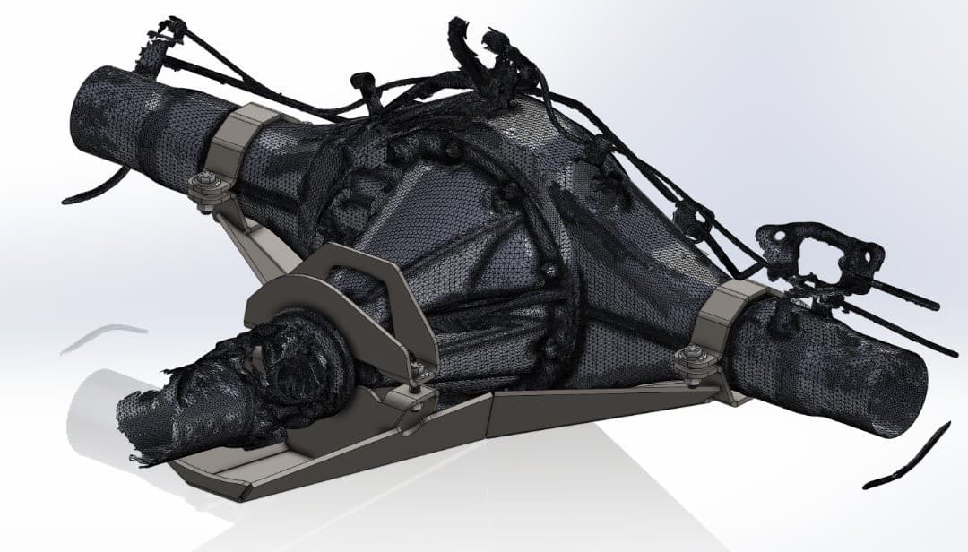
Full CAD of a complex casting is a lot of modeling, and often you don't need it. If you're designing a bracket, skid plate or mount that bolts to a casting, you need the mounting faces, hole positions and sizes, bores and axes. The rest can stay mesh.
Key features only CAD means we fit those features to the scan: planes on mounting faces, cylinders on tubes and bores, holes with their positions and diameters, and the axes and reference points that tie them together. Each fitted feature is calculated from many scan points, so it's a cleaner reference than a single caliper reading. You get the features as CAD (STEP or X_T) alongside the mesh, so you can mate to real geometry and still see everything else.
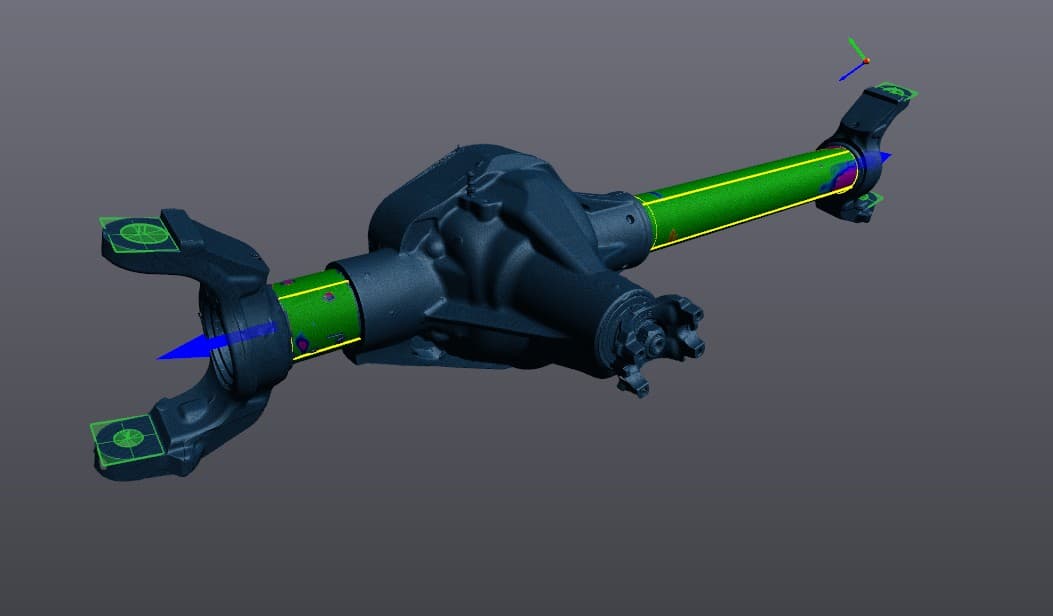
That's how a lot of off-road and motorsports design gets done. The axle housing stays a scan, and the new parts are real CAD designed around it.
For more on how the modeling works, read our guide to scan-to-CAD reverse engineering.
Watch for "STEP files" that are really meshes
Free converters can wrap an STL inside a STEP file. Every triangle becomes its own face, so the file is huge, slow to open and still not editable in any useful way. A real STEP deliverable from a scan is modeled: a hole is one cylindrical face, not hundreds of triangles.
Format doesn't guarantee accuracy either. The mesh is the measured data, and CAD is a model built to it. Ask for the CAD to be checked against the scan so you know how closely the model follows the part.
What to ask for when you order a scan
Tell us what the file is for and we'll recommend the deliverable. Most jobs land in one of three:
- Mesh only (STL, OBJ or PLY) for printing, visualization, clearance checks or inspection data.
- Mesh plus key features (STEP or X_T) for designing parts that mount to the scanned part.
- Full CAD plus mesh (STEP, X_T or IGES) for machining, tooling, drawings or design changes.
Scan time depends on size and complexity. Our published guide puts a small, simple part with a raw mesh at about half an hour of scanning, and complex surfaces or many features at 2–3 hours. Modeling CAD adds engineering time on top. To see where your part lands, get an instant estimate.