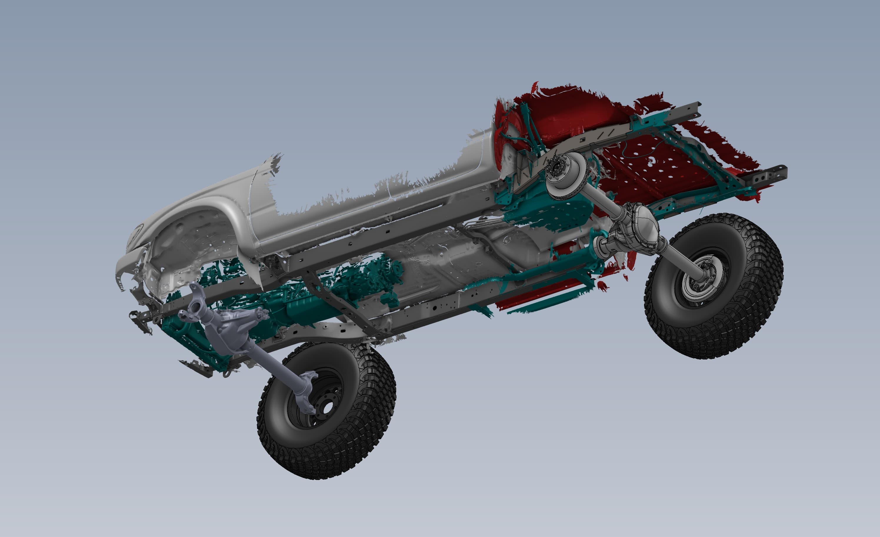
A solid-axle swap touches almost everything under a truck: frame, floorpan, fuel tank, drivetrain and bed. On this 1st-gen Toyota Tacoma we covered the whole cycle. We 3D scanned the chassis, designed a front solid-axle setup and a rear 4-link directly on the scan in CAD, and the rear 4-link was then fabricated and mounted on the truck. It's scan, design and build on one vehicle, with the scan as the common reference.
Scanning the whole chassis
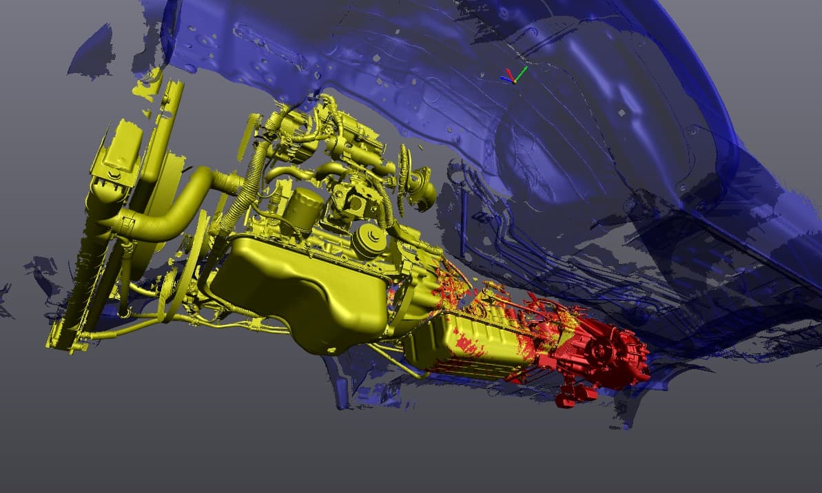
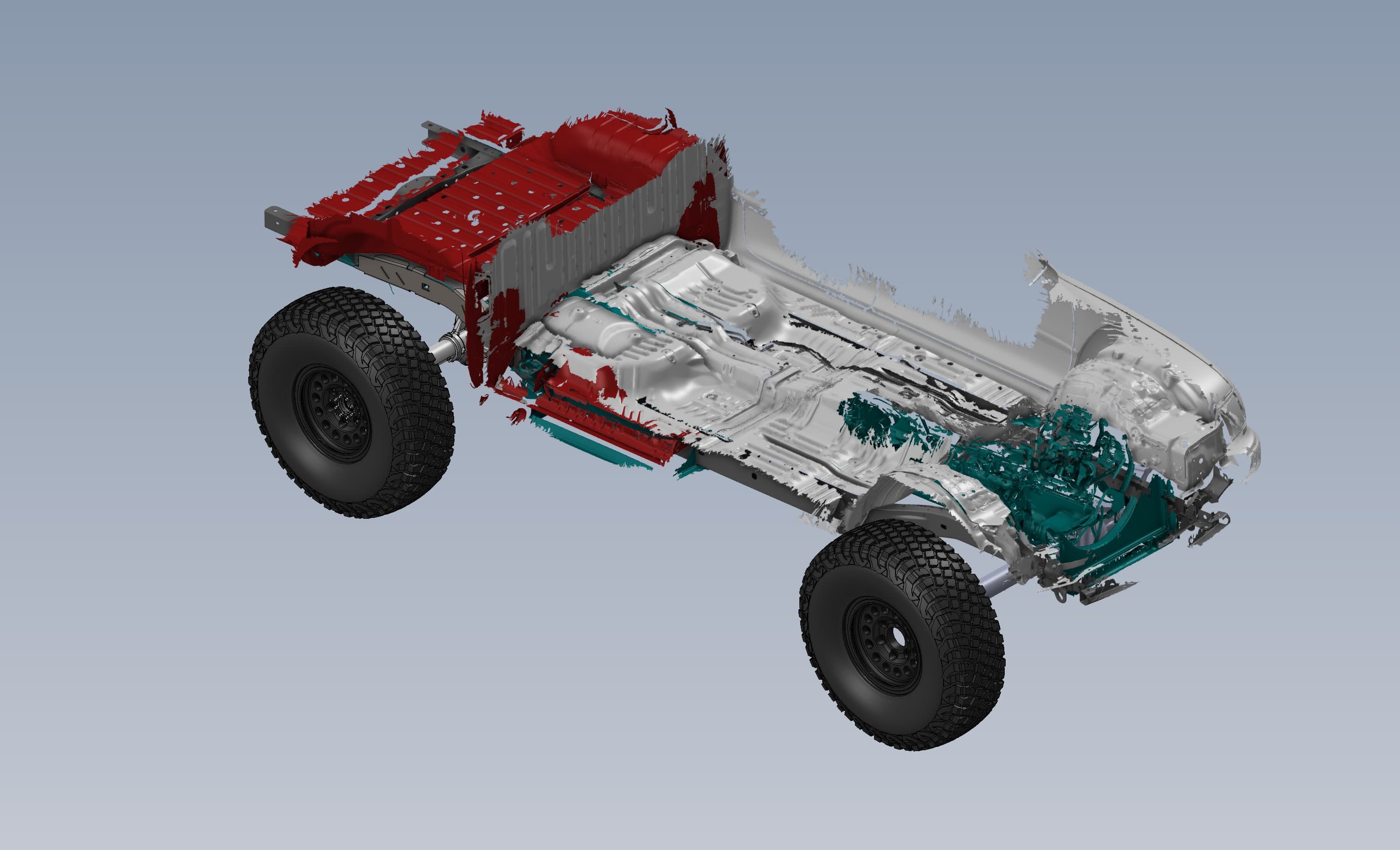
The truck was scanned from the frame up: ladder frame, crossmembers, spring hangers, cab floor and firewall, engine, transmission, transfer case and bed floor. All of it came in as one aligned dataset, so every part sits exactly where it does on the truck relative to everything else.
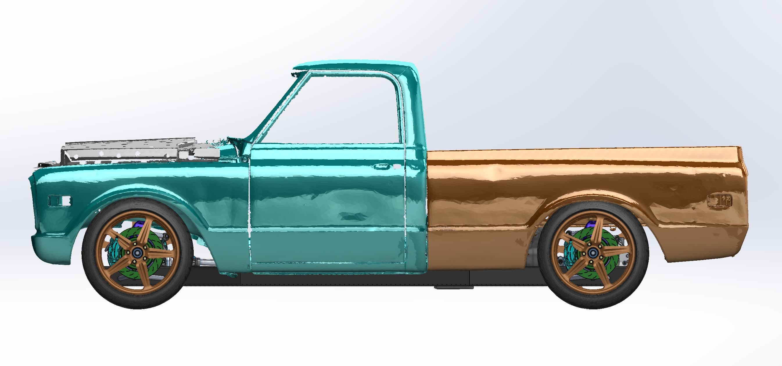
Then the scan was split by system. The frame was separated into front horns, mid-section and rear section. The powertrain was isolated from the floorpan above it. Color-coding each piece makes it easy to hide what you don't need and work on what you do, like designing frame brackets with the body turned off.
Turning scan data into design references
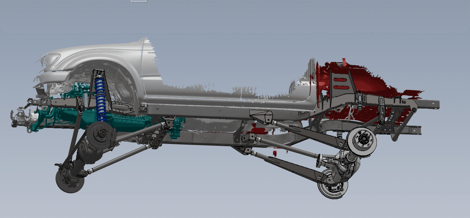
A mesh shows you the shape. A design needs references: axes, planes and points you can dimension from. For the front axle, we fitted geometry directly to the scan. Cylinders went on both axle tubes, and planes and circles marked the upper and lower ball-joint bosses on each knuckle.
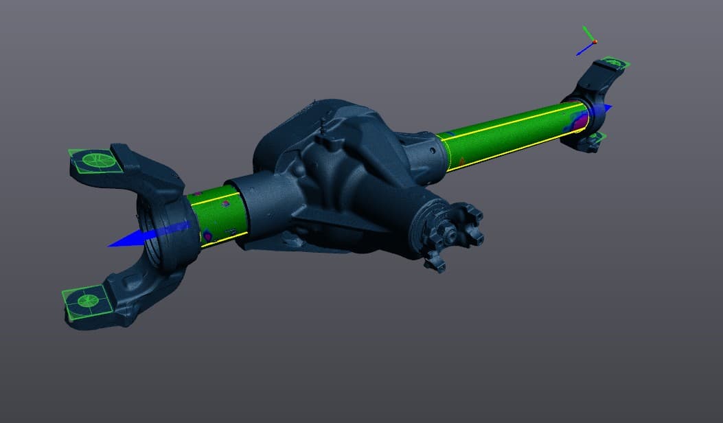
The frame got similar treatment, with a reference plane fitted between the rails. Those features give the new suspension real numbers to work from, like the axle tube axes, ball-joint locations and a frame reference plane, instead of measurements taken with a tape under the truck.
Designing the rear 4-link on the scan
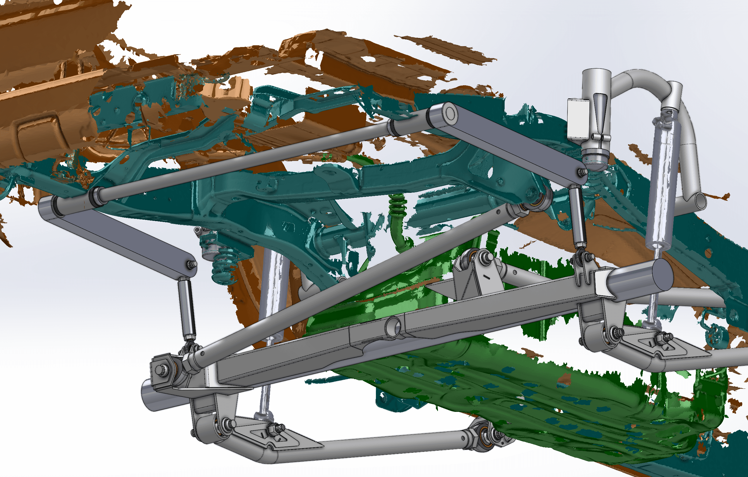
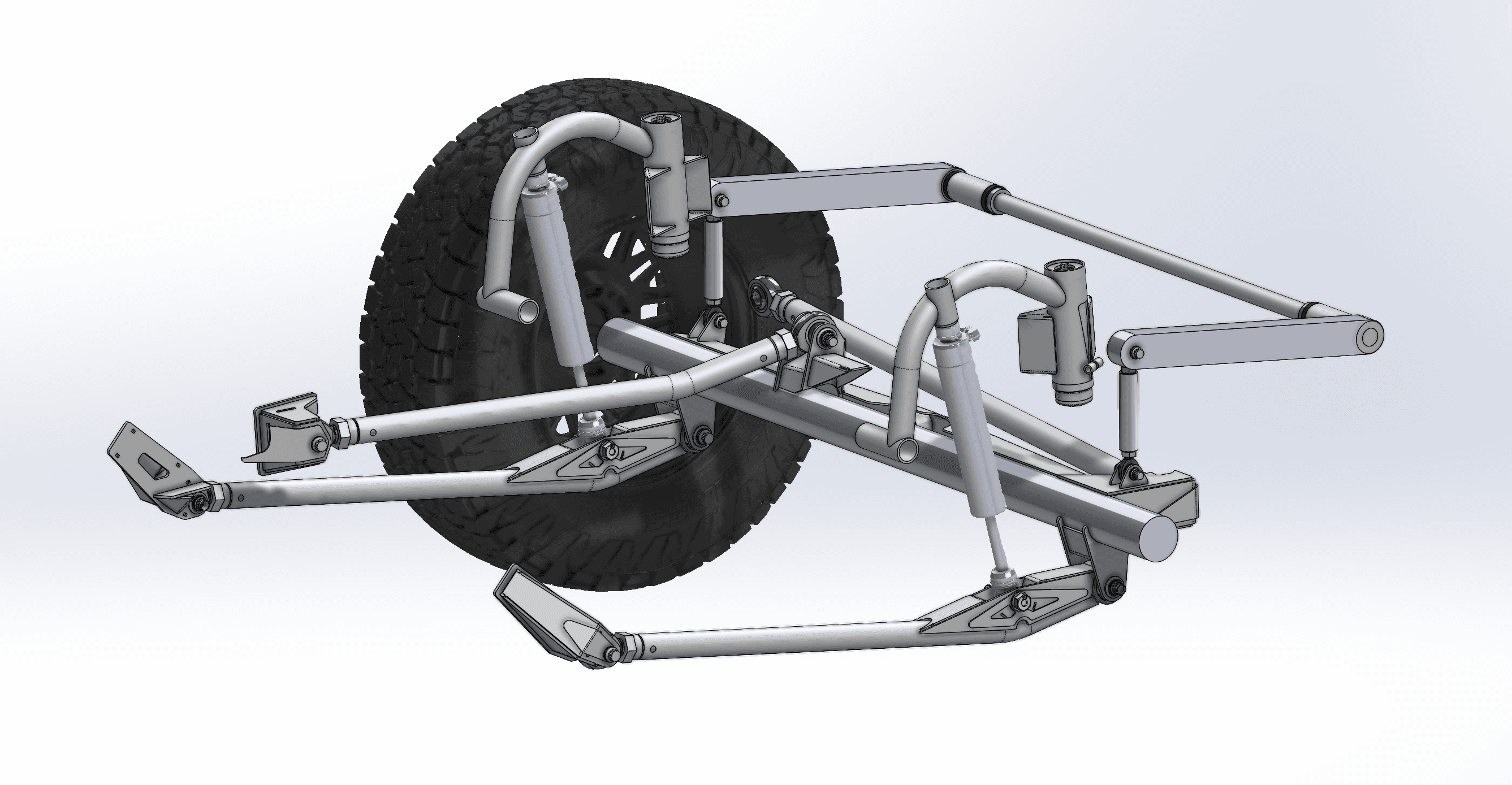
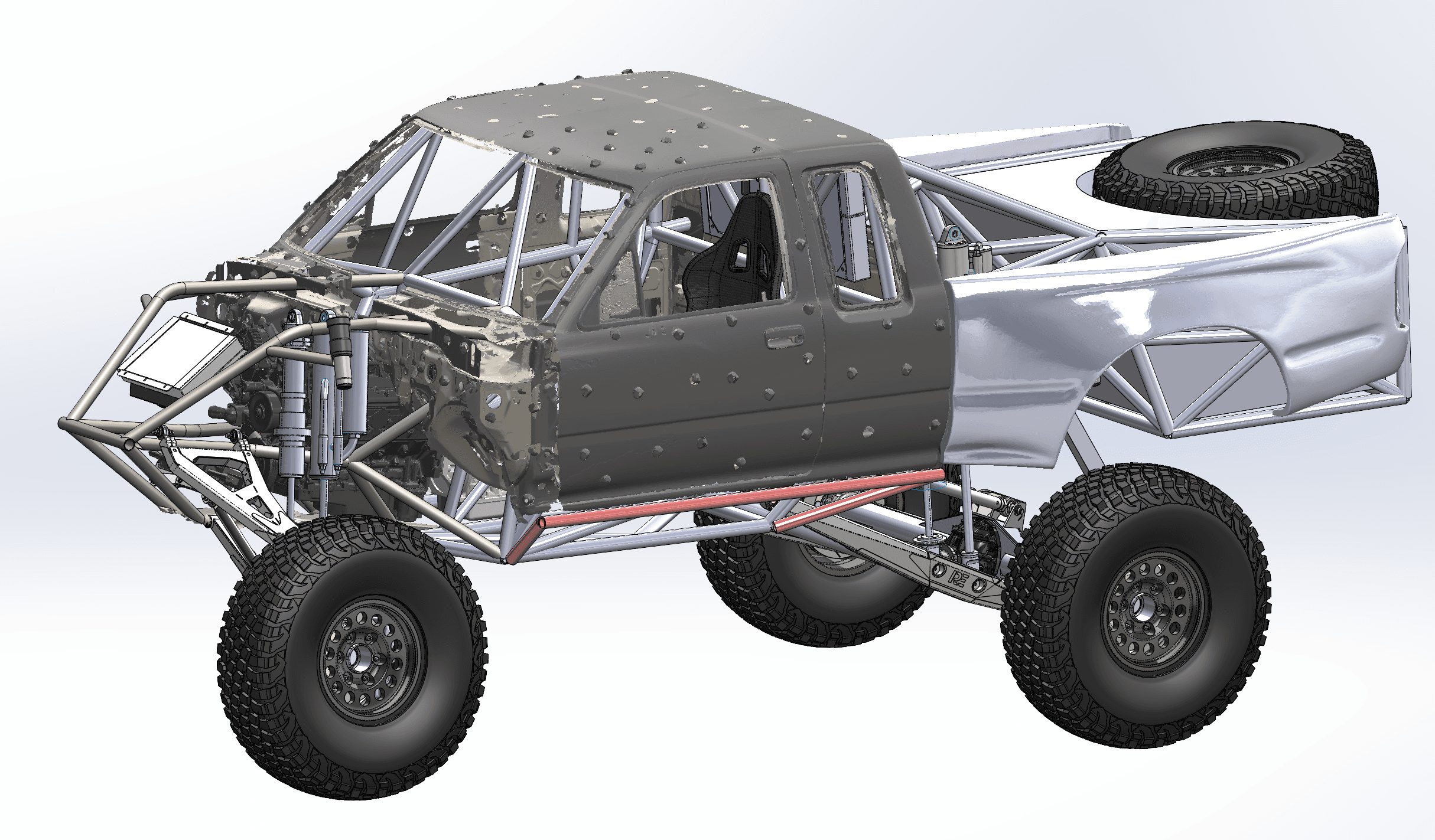
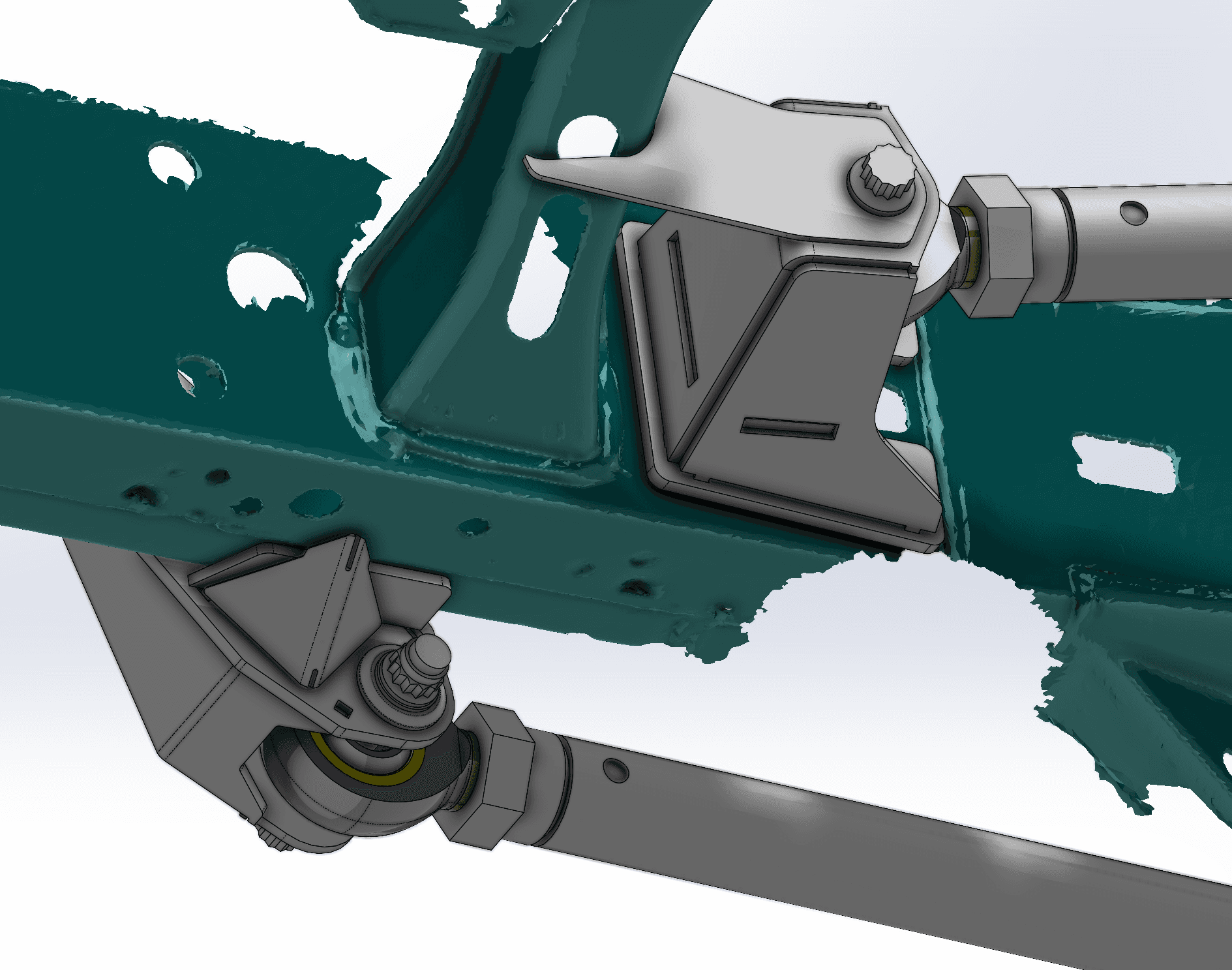
The rear suspension was designed right on the scanned frame:
- Triangulated upper and lower links with rod ends
- Frame-side link brackets with tab-and-slot construction
- Curved shock hoops carrying coilover and bypass shocks
- A tubular crossmember and a splined anti-roll bar
With the fuel tank and underbody in the scan, link and shock clearance to the tank could be checked from below before anything was cut. The brackets were drawn to sit on the real frame surface, holes and all.
From CAD to the truck
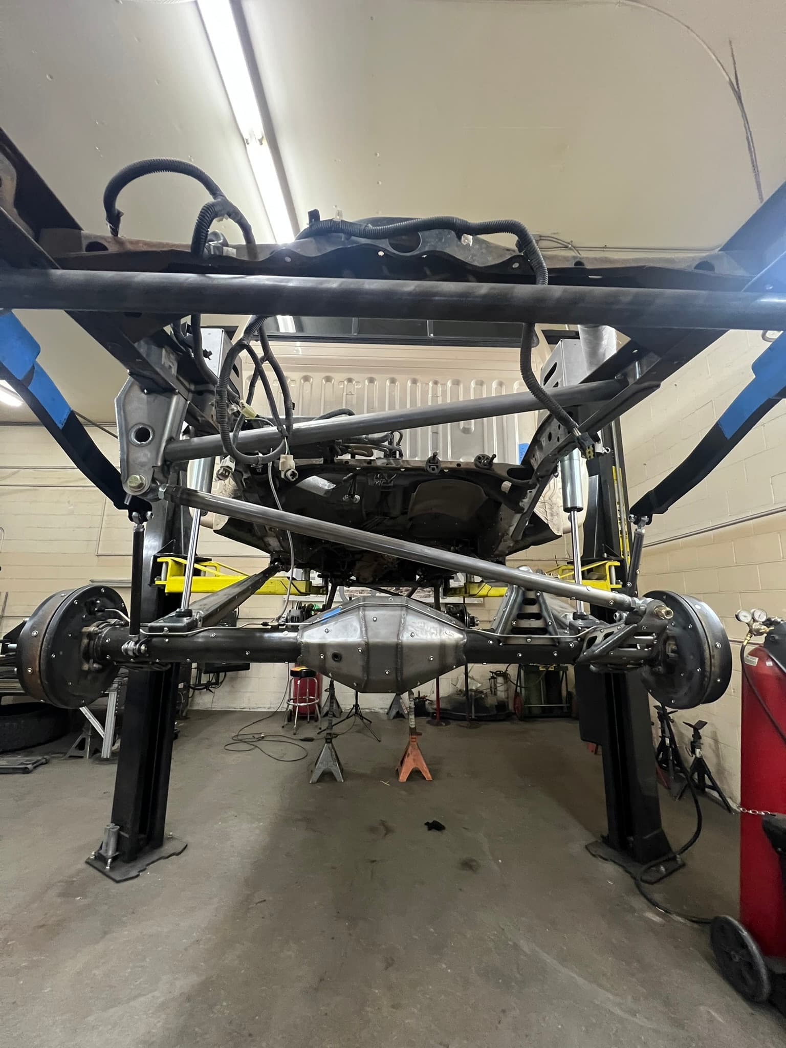
By July 2025, the rear 4-link had been fabricated and was under the truck: a plated rear axle housing, triangulated links, a tubular crossmember and coilover shocks, with remote-reservoir shocks on fabricated towers. Up front, the solid axle was in mock-up on jack stands. The rear suspension under the truck follows the triangulated 4-link layout designed on the scan.
Why scan before a solid-axle swap
Swaps go wrong in the details: a link bracket that lands on a frame seam, a shock that hits the fuel tank at full bump, a driveshaft that runs out of room. A full-chassis scan puts the real truck in CAD, so those details get solved on screen.
Our scan-to-CAD reverse engineering guide explains the feature-fitting step in more depth, and the reverse engineering service covers scanning and design for your build. See more automotive 3D scanning projects, or get an instant estimate for scanning your truck.