Aerospace 3D scanning captures the as-built shape of aircraft parts, engines, cockpits and tooling as accurate digital geometry. Aviation teams use it when drawings are missing, out of date or held by an OEM that no longer supports the airframe. Typical jobs: reverse engineering a legacy part, laying out a cockpit or interior retrofit, documenting an engine, designing tooling and ground-support equipment, and comparing what was built with what was designed.
One point matters more than the rest: a scan supplies geometry, not approval. The scan and the CAD model built from it feed your engineering and approval process. Whether a part can be made, installed or returned to service stays with your certified organization. With that clear, aircraft 3D scanning removes a lot of hand measuring, guessing and rework. Below are the applications where it pays off, what on-site work at a hangar or on a ramp involves, and two aerospace jobs we've done at Revv Engineering.
Where aircraft 3D scanning pays off
Legacy and out-of-production parts with no drawings
Older aircraft keep flying long after their parts stop being made. The OEM may be gone, the drawings may never have been released, or the part in your hand may no longer match the drawing after years of repairs. 3D scanning aircraft parts gives your engineers the real geometry, including freeform fairings, ducts, castings and formed brackets that are slow and error-prone to measure by hand.
You get the mesh as the as-scanned record and a CAD model in STEP, Parasolid (X_T) or IGES that your engineering can turn into drawings. A worn or damaged part is not the design, so tell us what's worn: the model can follow the intended shape while the scan documents what actually came off the aircraft. Scan the mating part too when you can. It often settles what the nominal should be.
Cockpit, cabin and interior retrofit work
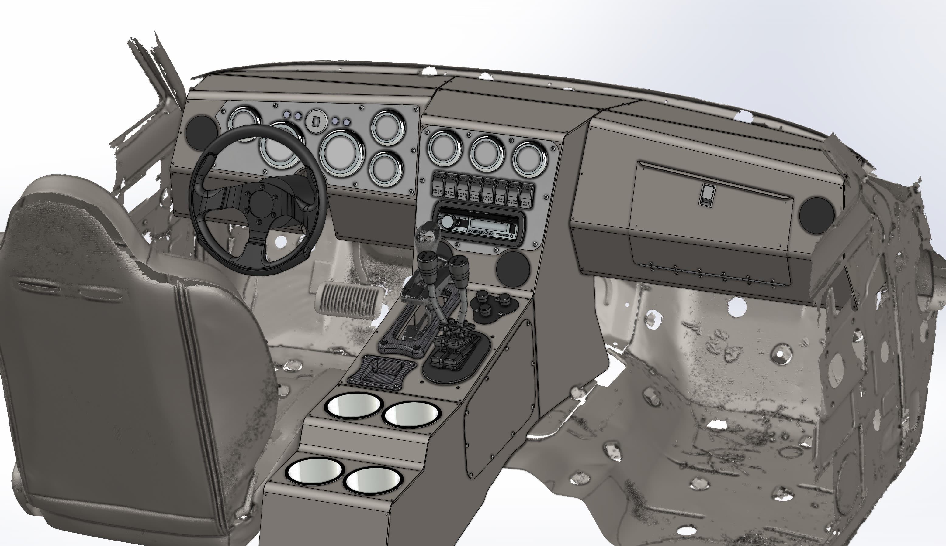
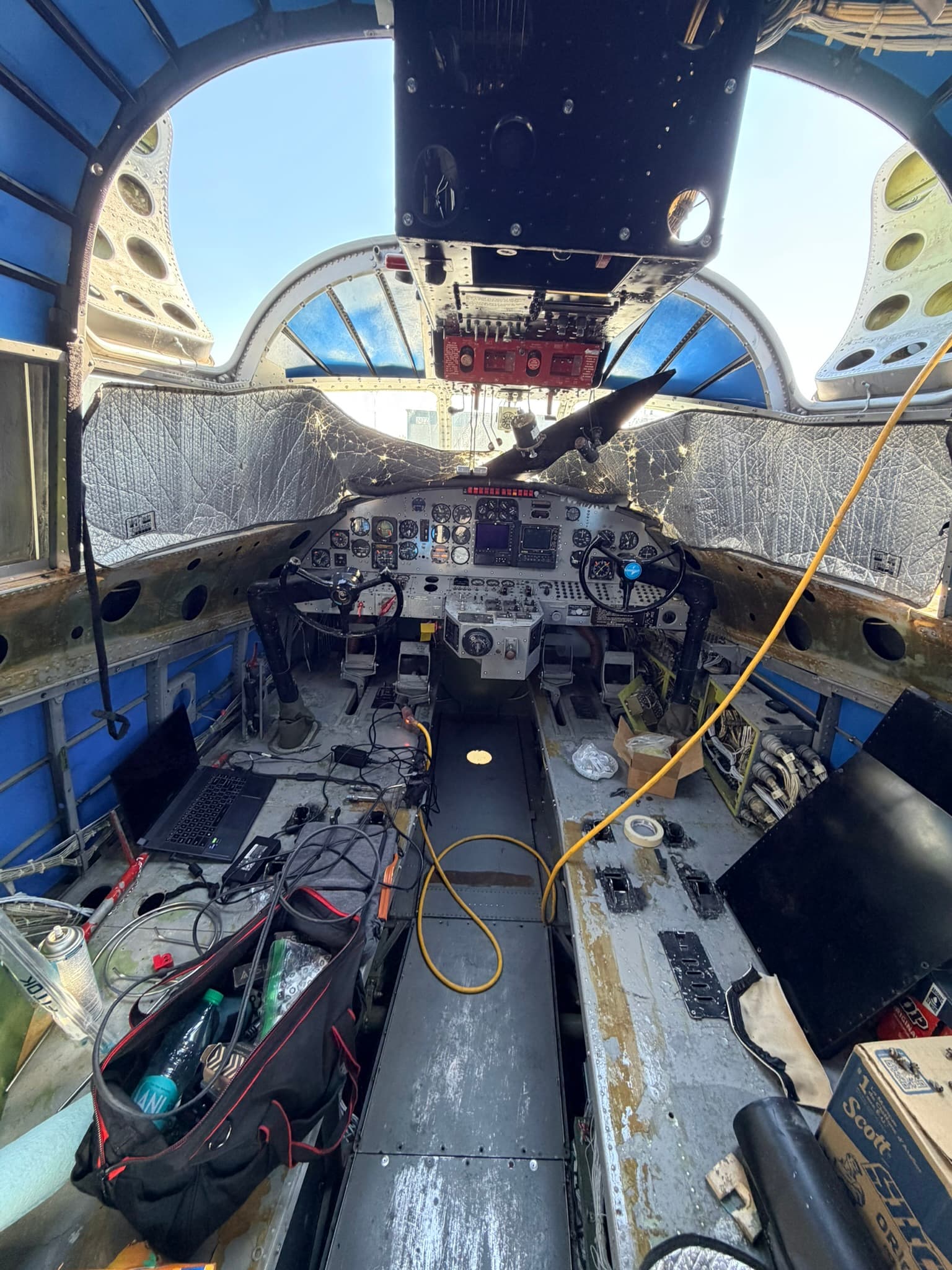
Panel upgrades, avionics installs, interior refurbishments and seat or monument changes all start with the same question: what space is actually there? Scanning the cockpit gives your designers the real instrument panel, glareshield, structure, control positions and the volume behind the panel. New panels and interior parts get designed to the airframe you have, not to an old drawing.
We scanned an amphibian aircraft's cockpit and instrument panel on an airport ramp with the cabin stripped back to structure. That's the best time to capture an interior, because nothing hides the structure you'll be mounting to.
Engine and component documentation
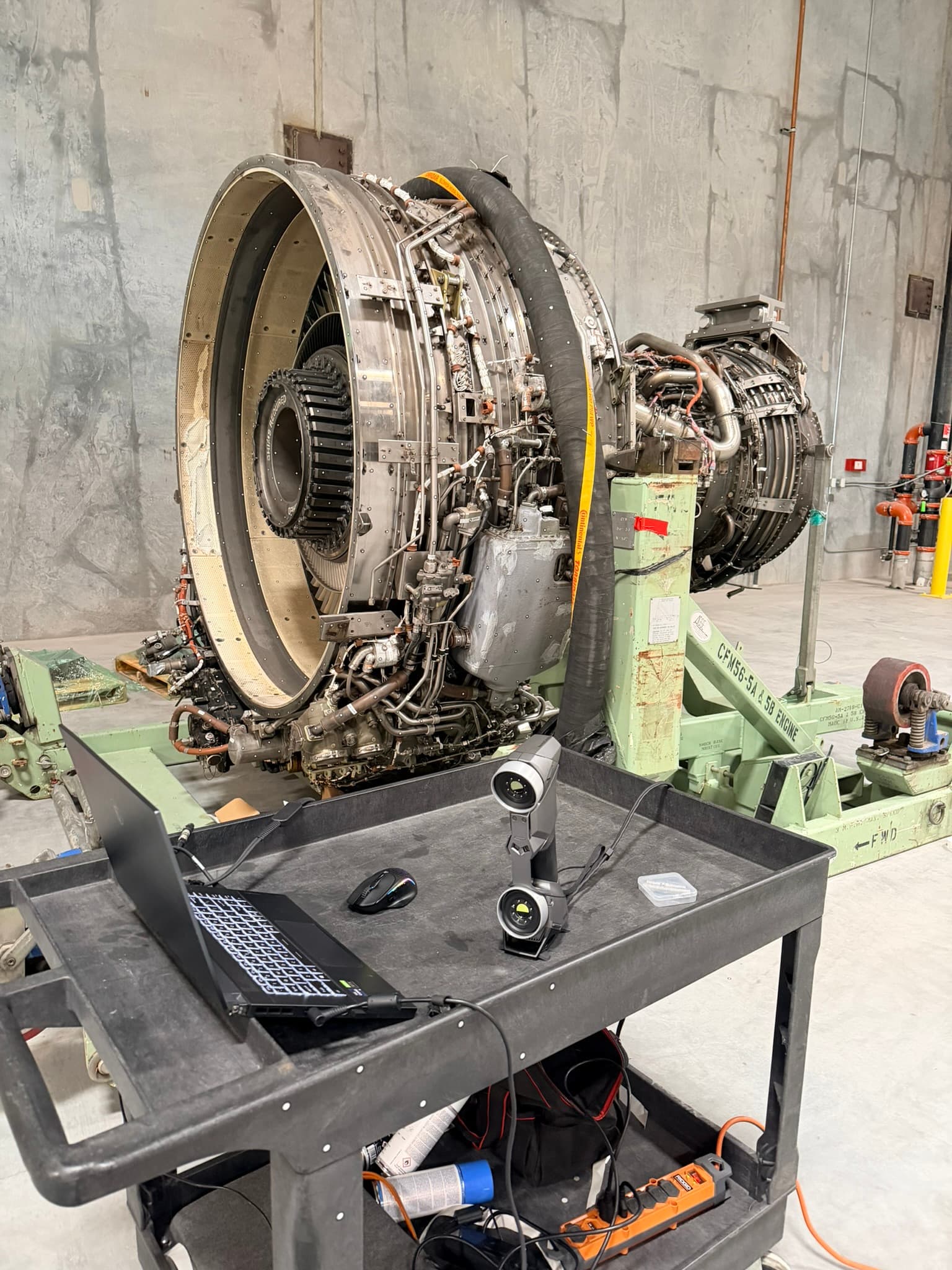
Engines and large components are expensive to move and awkward to measure. A scan captures the external envelope, mounts, plumbing and harness routing in one session, which helps when you're designing stands, covers, cradles or installation hardware, or keeping a record of condition. We scanned a CFM56-series turbofan for an aviation customer in place on its transport stand.
Tooling, fixtures and ground-support equipment
Jigs, holding fixtures, drill templates, work platforms, covers and ground-support equipment all have to fit the aircraft or part they serve. Scan the interface (a fuselage contour, a wing root fairing, a set of mounting points) and design the tooling to it. Worn tooling that was never drawn can be scanned and modeled so it can be remade.
As-built vs. as-designed comparison
When you have the CAD nominal, a scan shows how the real part compares. You see a color deviation map across the whole surface instead of a handful of point checks. Use it on incoming parts, on a repaired contour, on tooling after rework, or to find out how far a legacy part has drifted from its drawing.
Vintage aircraft restoration
Restorers face all of the above at once: scarce parts, missing drawings, and skins, cowlings and fairings whose shape has to match. Scan a good surviving part, or the structure a new part has to fit, and record the airframe before it comes apart. The same rule applies here. The scan supports your restoration engineering, and approval stays with the people certified to give it.
What your engineering team gets back
- A mesh (STL, OBJ or PLY). This is the as-scanned record of the part, component or area: what was actually there before anything changed.
- CAD in STEP, Parasolid (X_T) or IGES, modeled in SolidWorks. This is the geometry your engineers use to make drawings, design a retrofit or build tooling.
- A deviation comparison when you supply a CAD nominal: a color map of where the scanned part differs from the design, and by how much.
What happens next, from drawings and analysis to conformity and approval, runs through your process. We supply the geometry and answer questions about how it was captured.
On-site scanning at the hangar or on the ramp
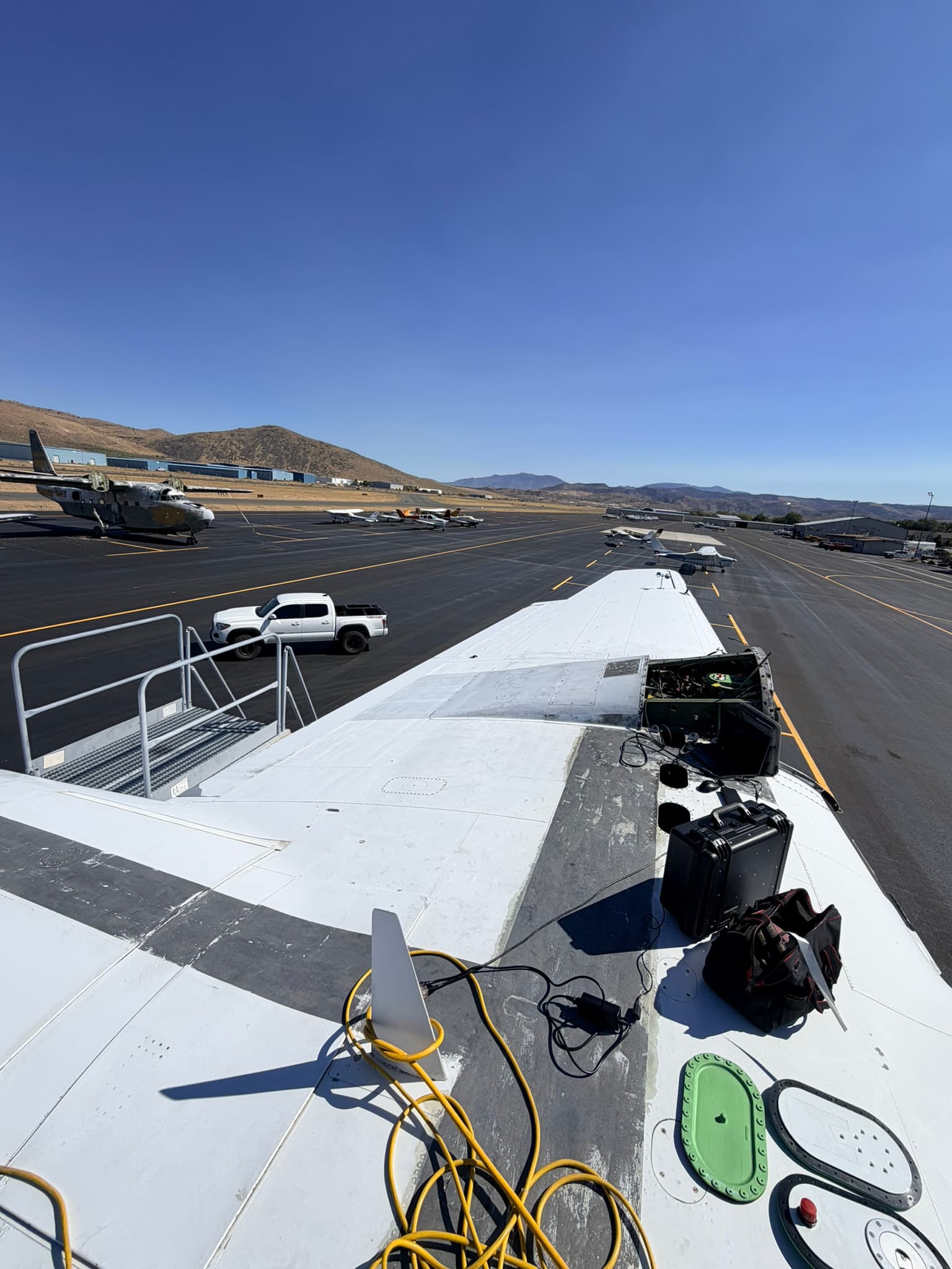
Most aerospace scanning happens where the aircraft is. Our on-site 3D scanning service brings handheld blue-laser and structured white-light scanners to your hangar, ramp or shop. A few things make the day go smoothly:
- Access and escorts. Tell us about badging, airside access, escort requirements and working hours ahead of time. We work to your escort's schedule.
- Power. The scanners and laptop run on standard power. Tell us where the nearest outlet is. On a ramp, we run an extension cord to the aircraft.
- Protecting surfaces. We stay on approved walkways, keep cases and tools off painted and no-step areas, and follow your rules on what can touch the aircraft. Positioning targets are small adhesive dots, and the sublimating scanning spray we use on shiny or clear surfaces disappears on its own. Confirm with your team before anything goes on a sensitive finish.
- Foreign object debris. Around engines and open intakes, treat targets like any other FOD risk: count them on and count them off.
- Light and weather. Direct sun and wind make ramp scanning harder, so plan for shade, a cooler time of day or a hangar slot when you can.
- Proprietary and export-controlled data. We're happy to work under your NDA and your data requirements, including where files are stored, how they're transferred and when they're deleted. If the hardware or data is export controlled, tell us in the first conversation so handling is agreed before anyone is scheduled. We don't publish photos, names or tail numbers without written permission.
What to send for an aerospace 3D scanning quote
- What the part, component or area is, with photos and a rough size
- Where it is (hangar, ramp or shop, and the city) and whether it can ship to us
- What the data is for: reverse engineering, retrofit design, tooling or inspection against CAD
- The formats your engineering uses: STEP, Parasolid (X_T), IGES or a mesh
- Any tolerance, access, escort or data-handling requirements
We're based in Reno, Nevada, serve Reno-Tahoe, Northern Nevada and Northern California, and travel anywhere in the US. Smaller parts can be dropped off in Reno or shipped to us. See more of our aerospace and aviation scanning work, or get an instant estimate for your part or aircraft.