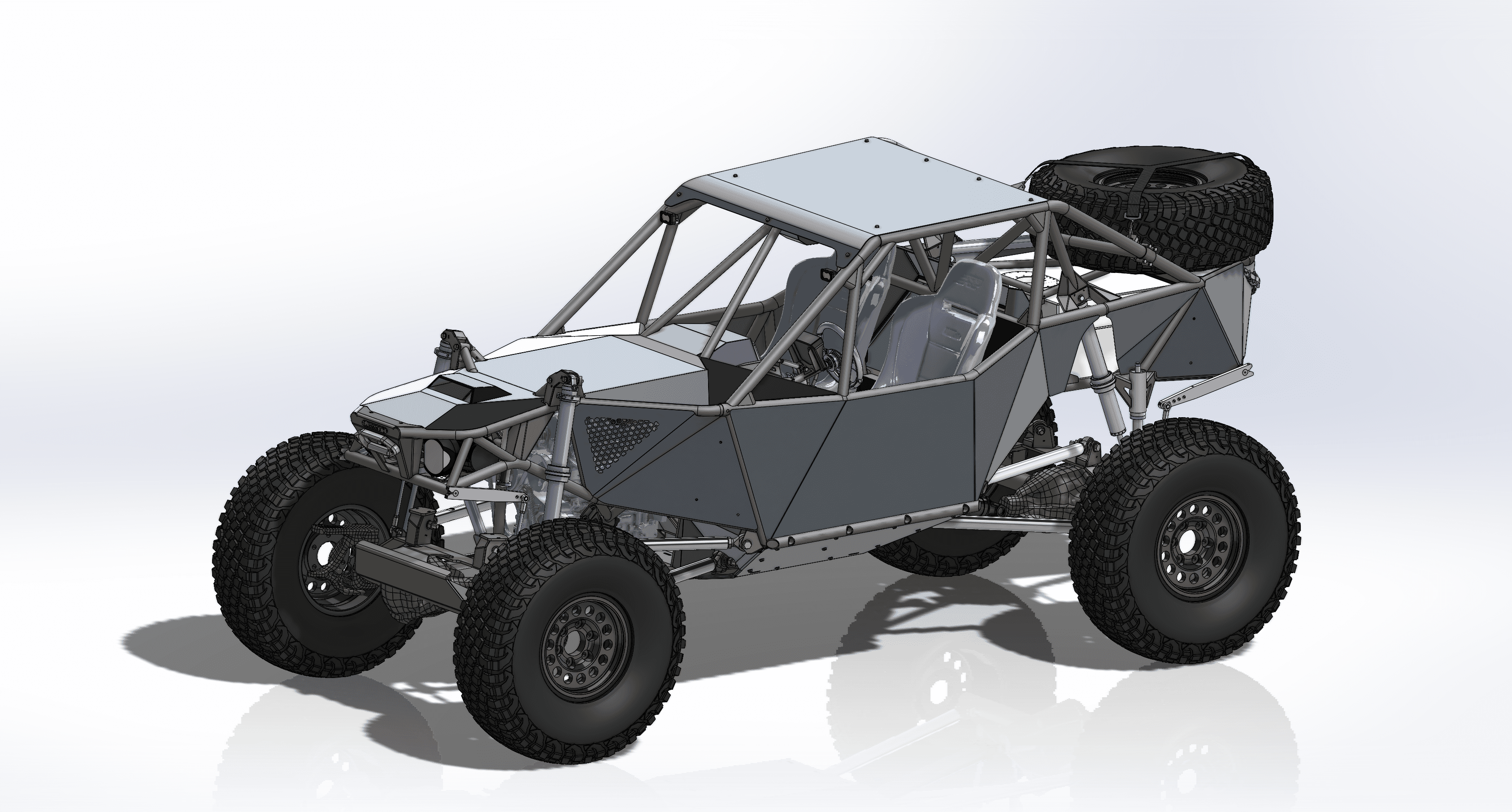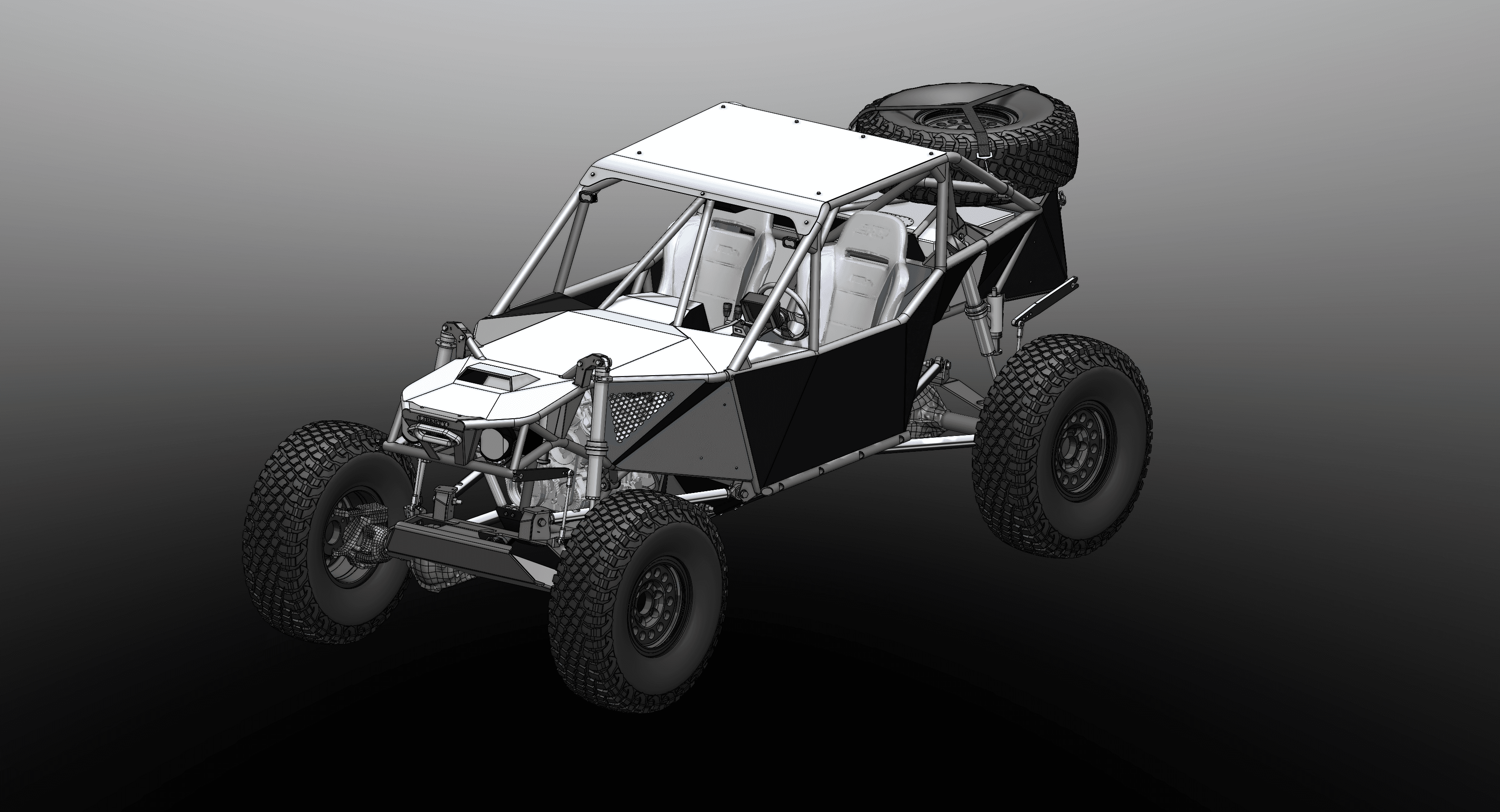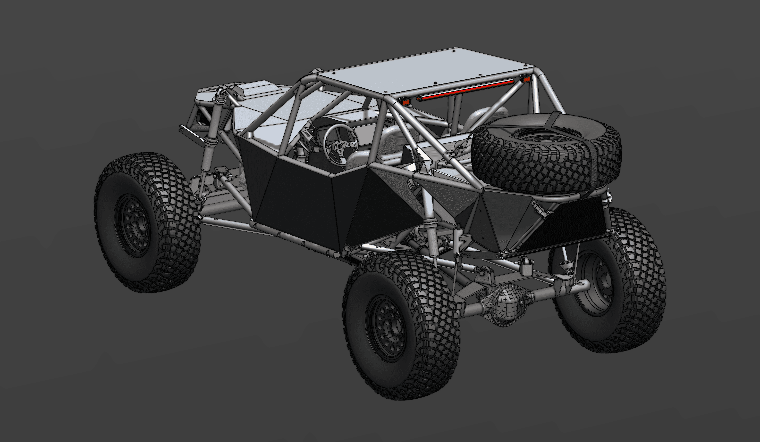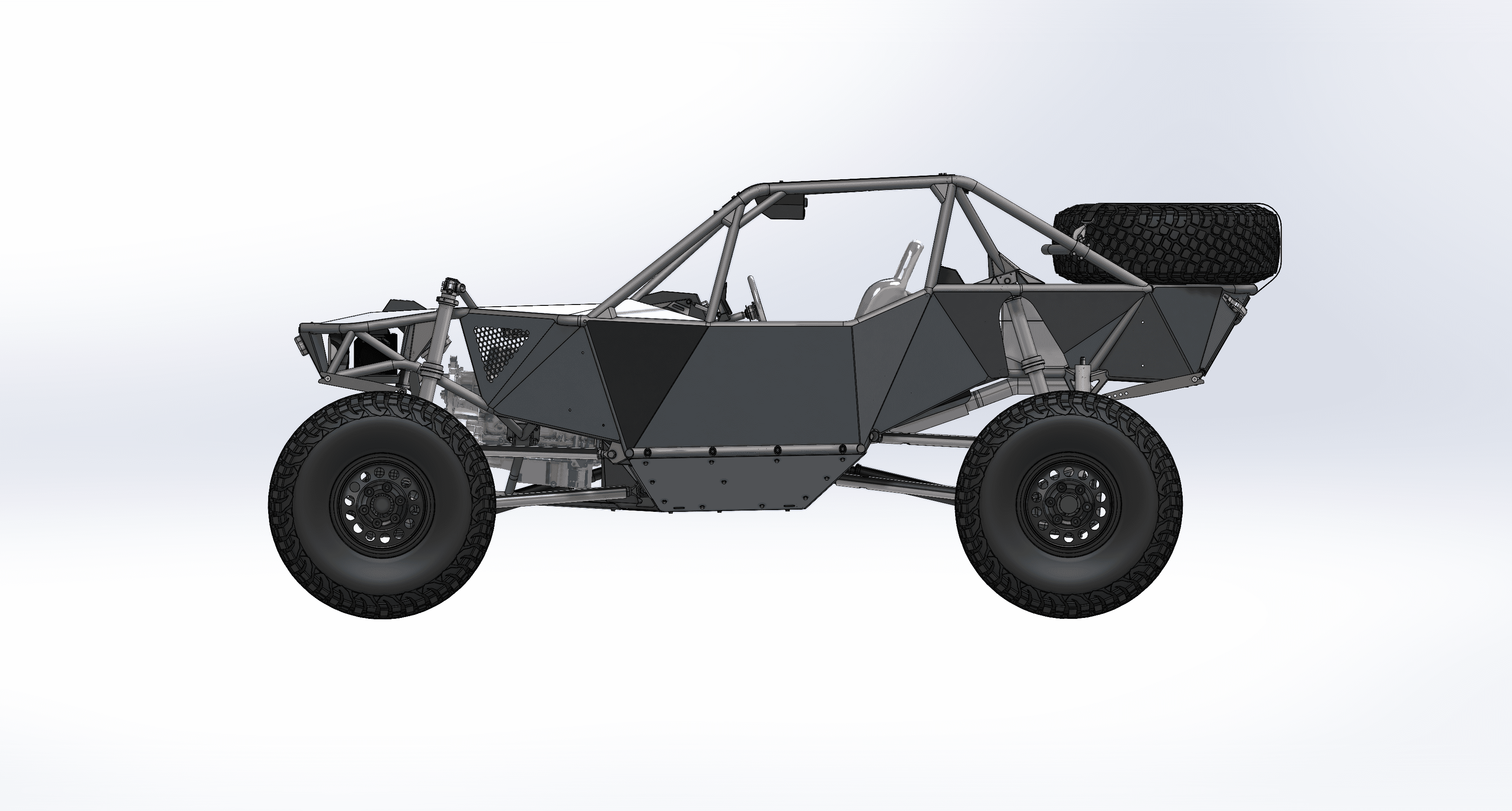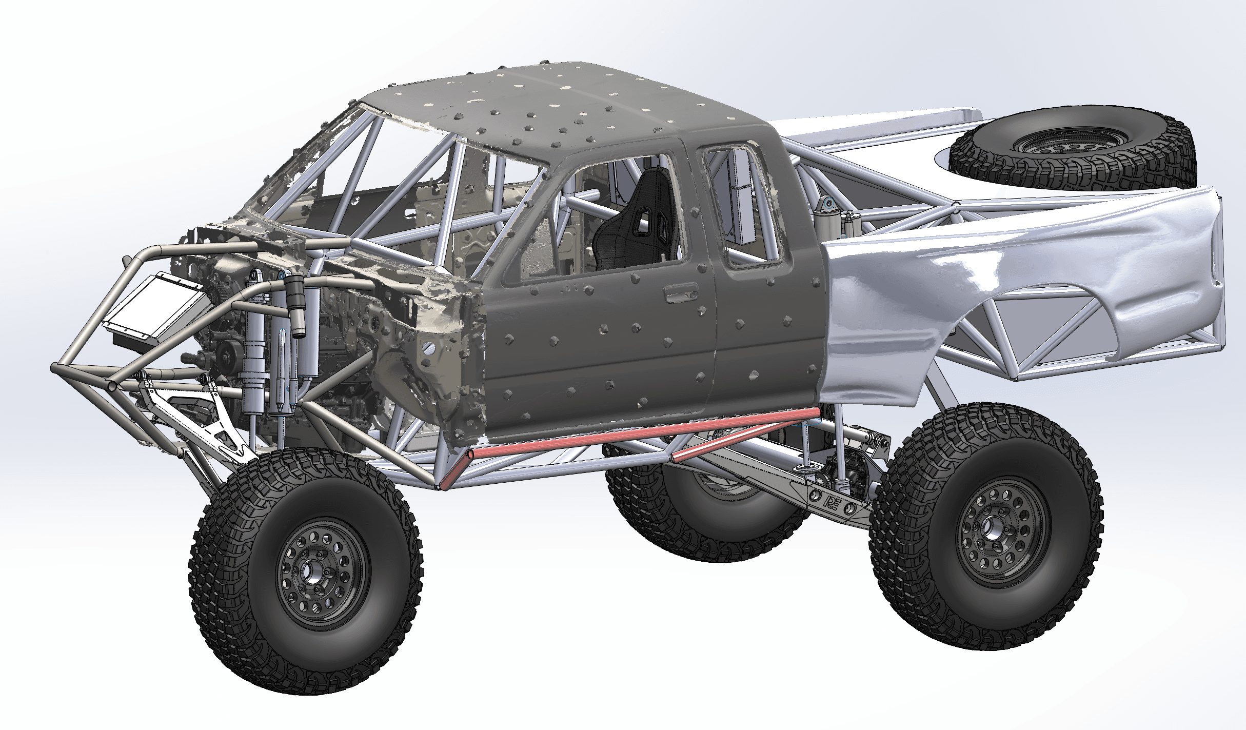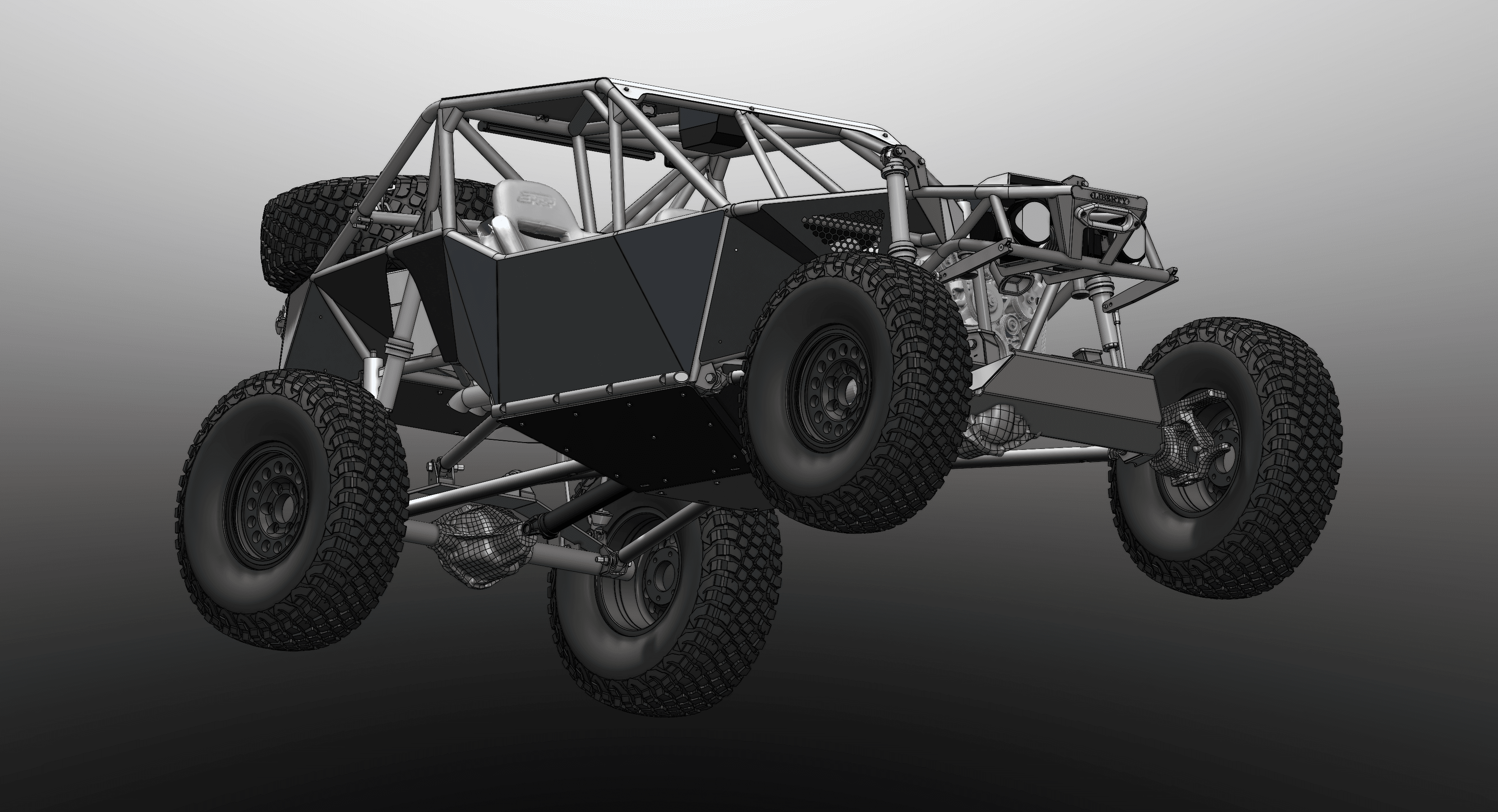
On a solid-axle race car, the axles move through the chassis every time the suspension cycles. The link mounts, shock mounts, skid plates and driveshaft all have to clear them. For this two-seat tube-chassis off-road race car, we 3D scanned the axle housings and dropped the scan meshes straight into the CAD assembly. The chassis, front and rear 4-link suspension and body were designed around the real housings instead of a simplified stand-in.
The challenge: packaging around moving axles
An axle housing is not a simple tube. It has a differential center section, brackets, and knuckle or hub ends, and on an off-road race car it swings through a big arc as the suspension travels. At full droop and full articulation, the housing, the pinion and the link mounts all end up somewhere new.
If the chassis is designed around a rough guess of the axle, the misses show up at the worst time: a skid that hits the diff, a link that binds, a driveshaft that runs out of room. Designing around the scanned housings puts the real shape in the model from day one.
Scanning the axles into the assembly
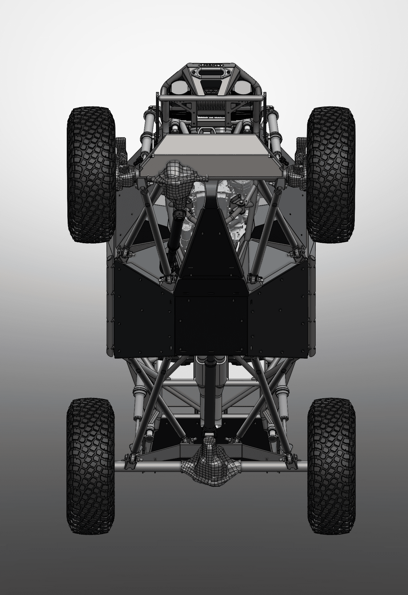
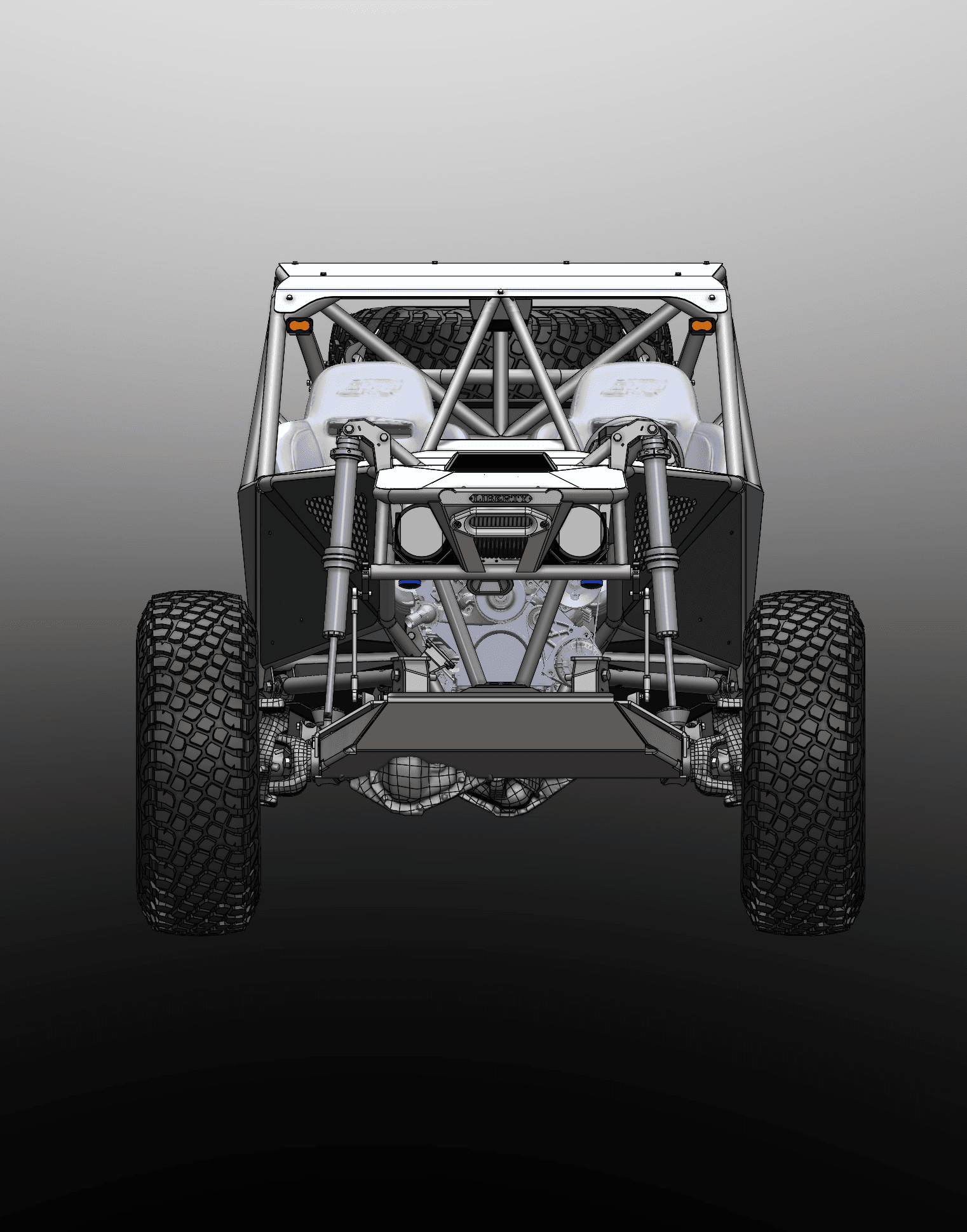
The axle housings were scanned and placed in the CAD assembly as meshes. You can see them in the renders: the housings have the faceted look of scan data, while everything new is smooth, modeled CAD. There was no need to rebuild every surface of a housing as solid geometry. The new parts only need to know where the housing is and where they attach.
Designing the car
With the axles in place, the rest of the car was designed around them:
- A two-seat tube chassis and cage with seats, steering wheel and dash display
- Angular sheet-metal body panels, a flat roof panel and a hood scoop
- Front and rear 4-link suspension with long-travel coilover and bypass shocks
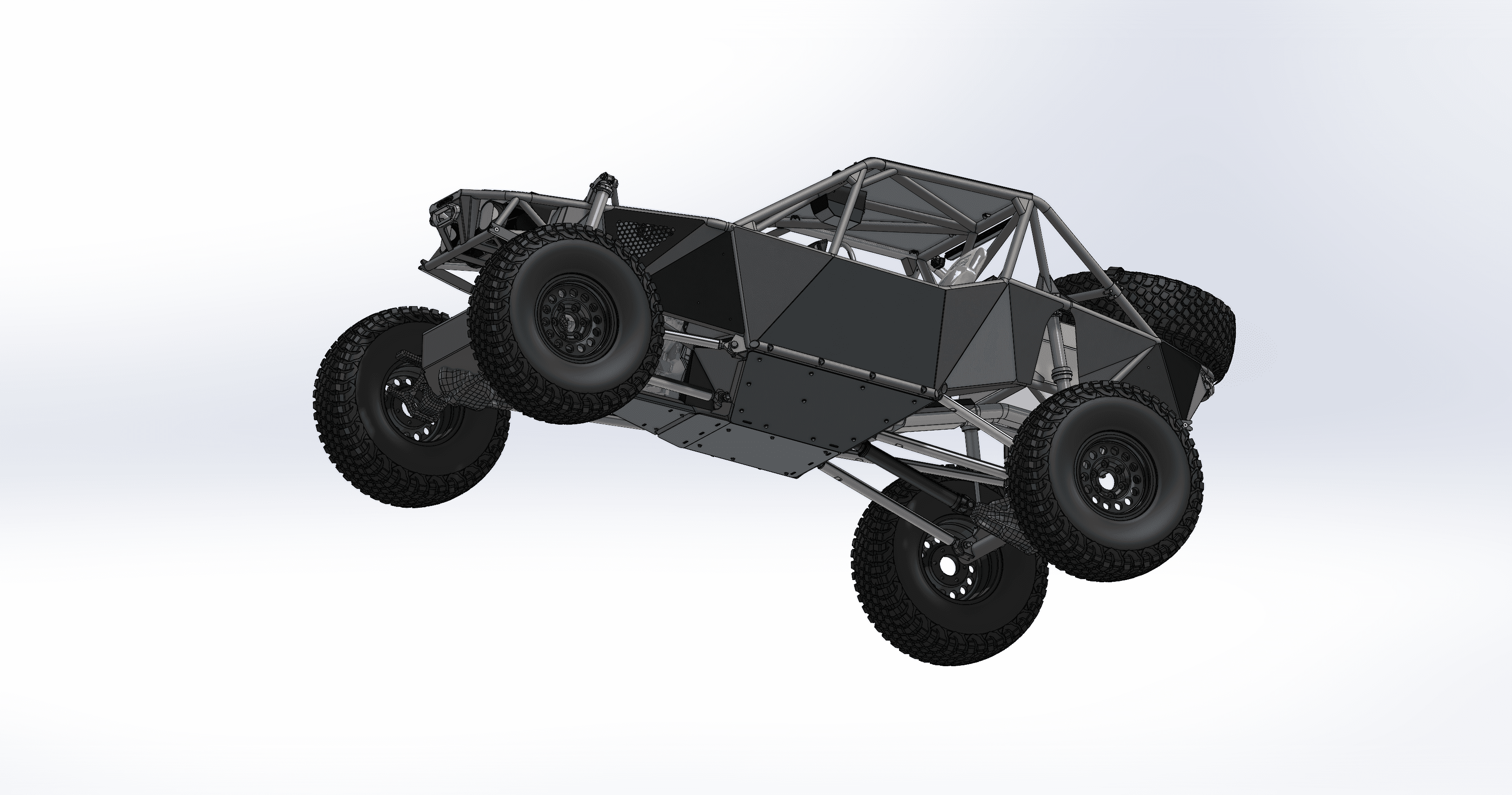
- Skid plates under the belly
- A front winch bumper, a rear-mounted spare tire and a red LED chase light bar
- Beadlock-style wheels on large off-road tires
Checking droop and articulation
With real housings in the model, the suspension can be posed at full droop and through articulation to check clearances, which is what the low-angle cover image and the droop render in the gallery show. The skids, link mounts and driveshaft are checked against the actual axle shape in each position. A problem found on screen is a quick CAD edit. The same problem found on the car means cut tubes and new brackets.
What came out of it
- Scan meshes of the front and rear axle housings
- A complete race car assembly in SolidWorks: chassis, cage, suspension, body and accessories
- Clearance checks at droop and articulation
- Renders for design review, on light and dark backgrounds
Designing a solid-axle car or buggy?
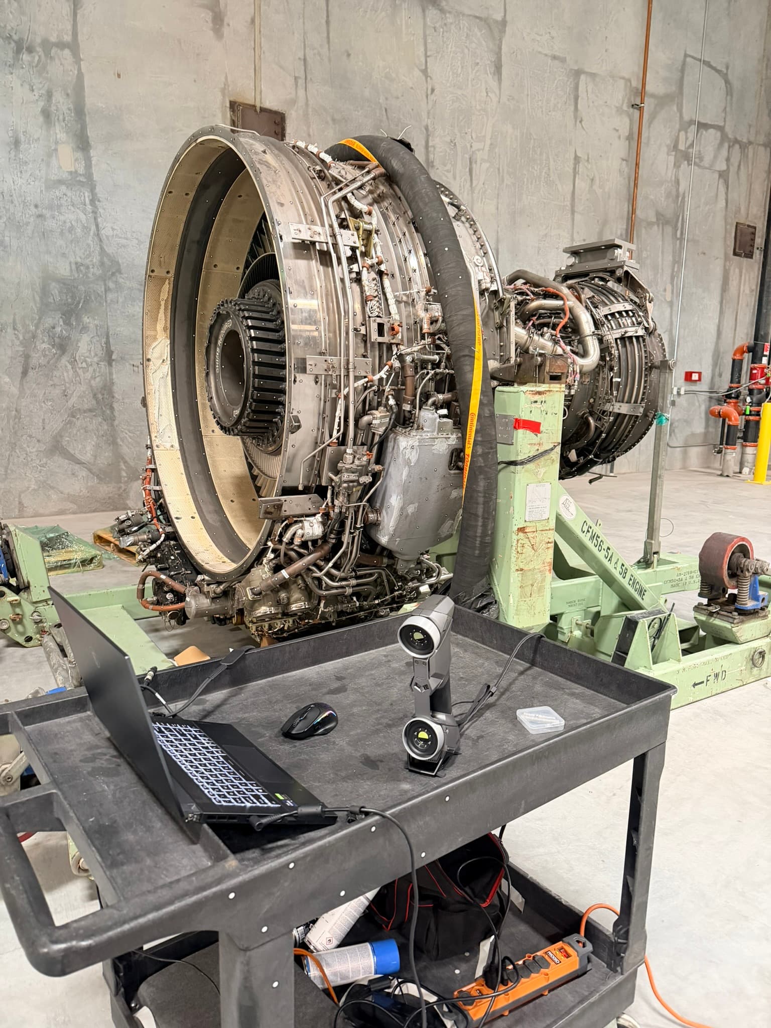
Start with the parts you're keeping. Axles, transfer cases, engines and steering boxes can all be scanned and dropped into your assembly so the new chassis fits them. Our 3D laser scanning service covers parts from a single housing to a full vehicle, and 3D scanning for motorsports shows how race teams use the data. See more motorsports projects, or get an instant estimate for scanning your axles.