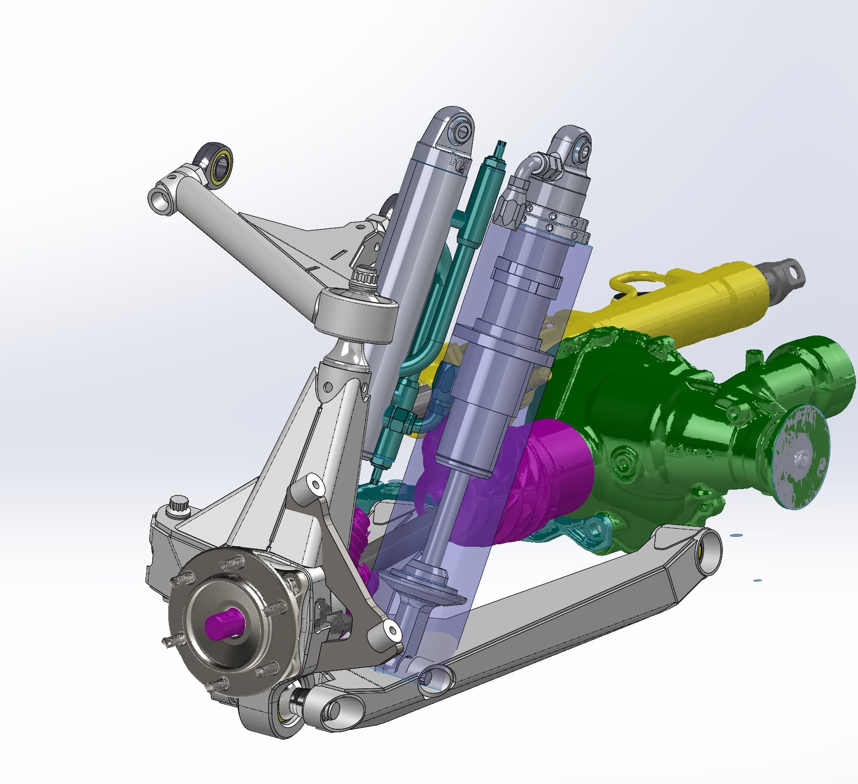
Long-travel front suspension has to work around parts that stay put: the differential, the steering rack and the CV axles. Put an arm in the wrong place and it hits the diff housing. Get the tie-rod geometry wrong and the steering fights the suspension. Push the travel too far and a CV boot gets stretched at droop. On this build, we 3D scanned the factory differential, steering rack and CV boots first, then designed the arms, shocks, upright and brake package around those meshes in CAD.
The parts that set the geometry
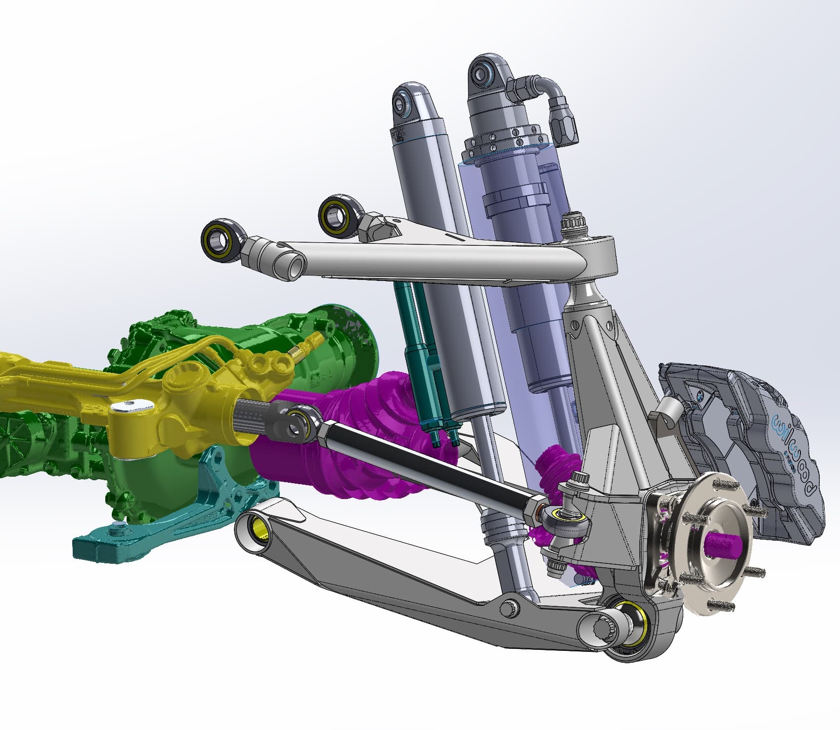
In the assembly, each scanned part has its own color so you can tell scan data from new design at a glance:
- Green: the front differential
- Yellow: the steering rack
- Teal: a mount
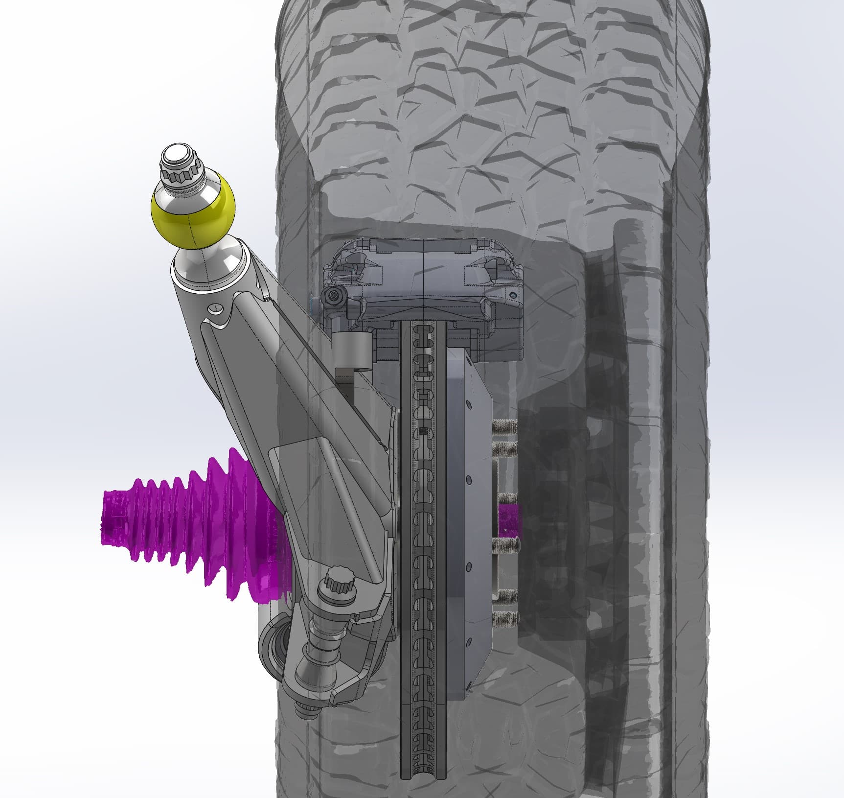
- Purple: the CV axle boots
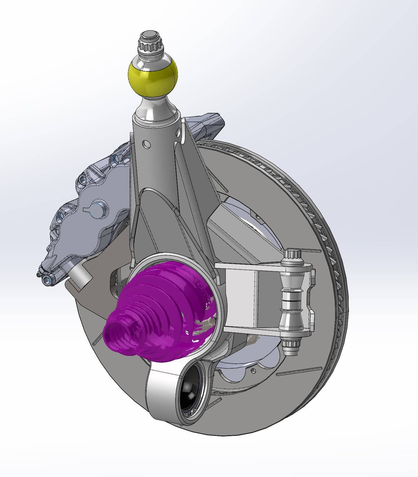
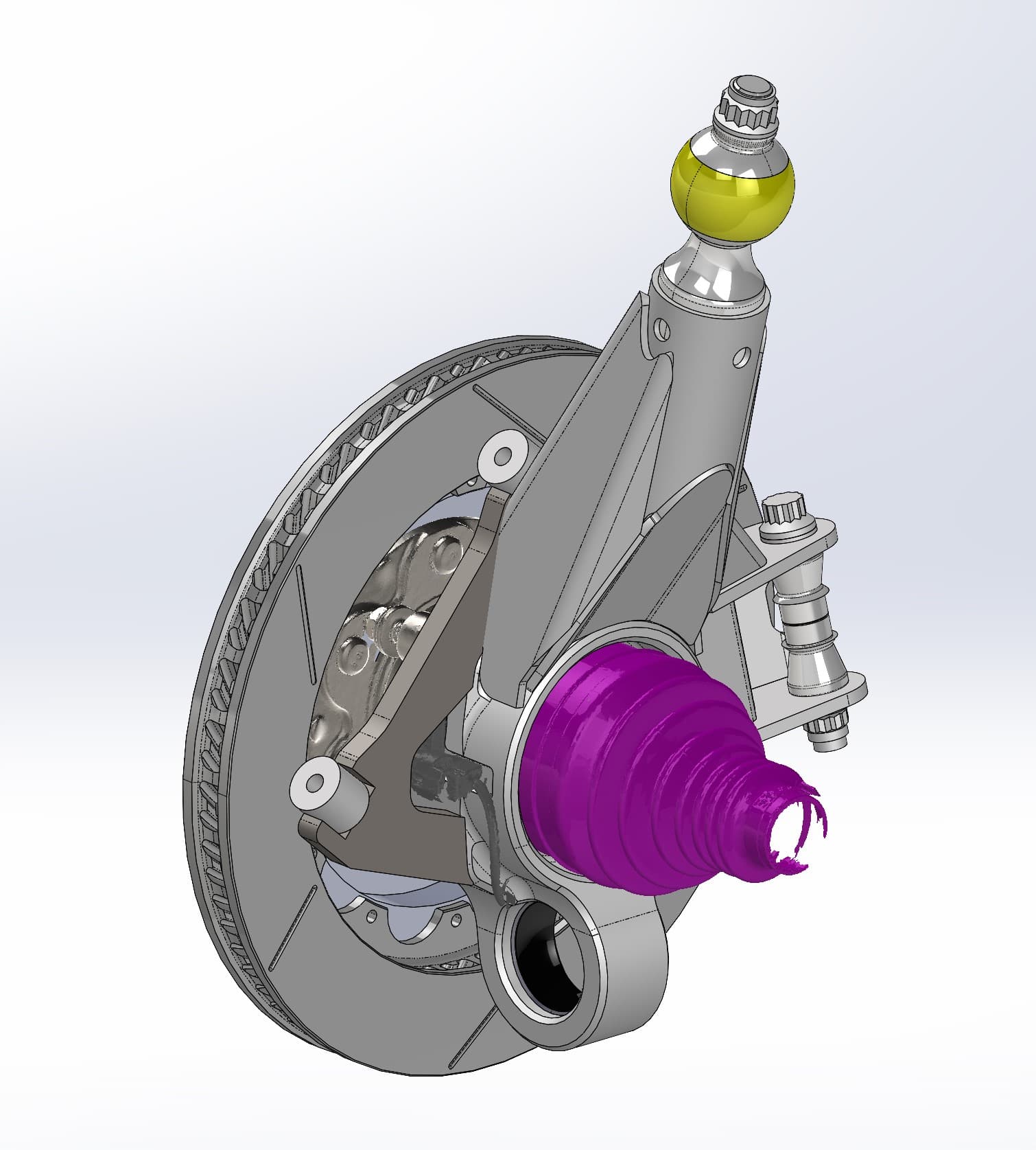
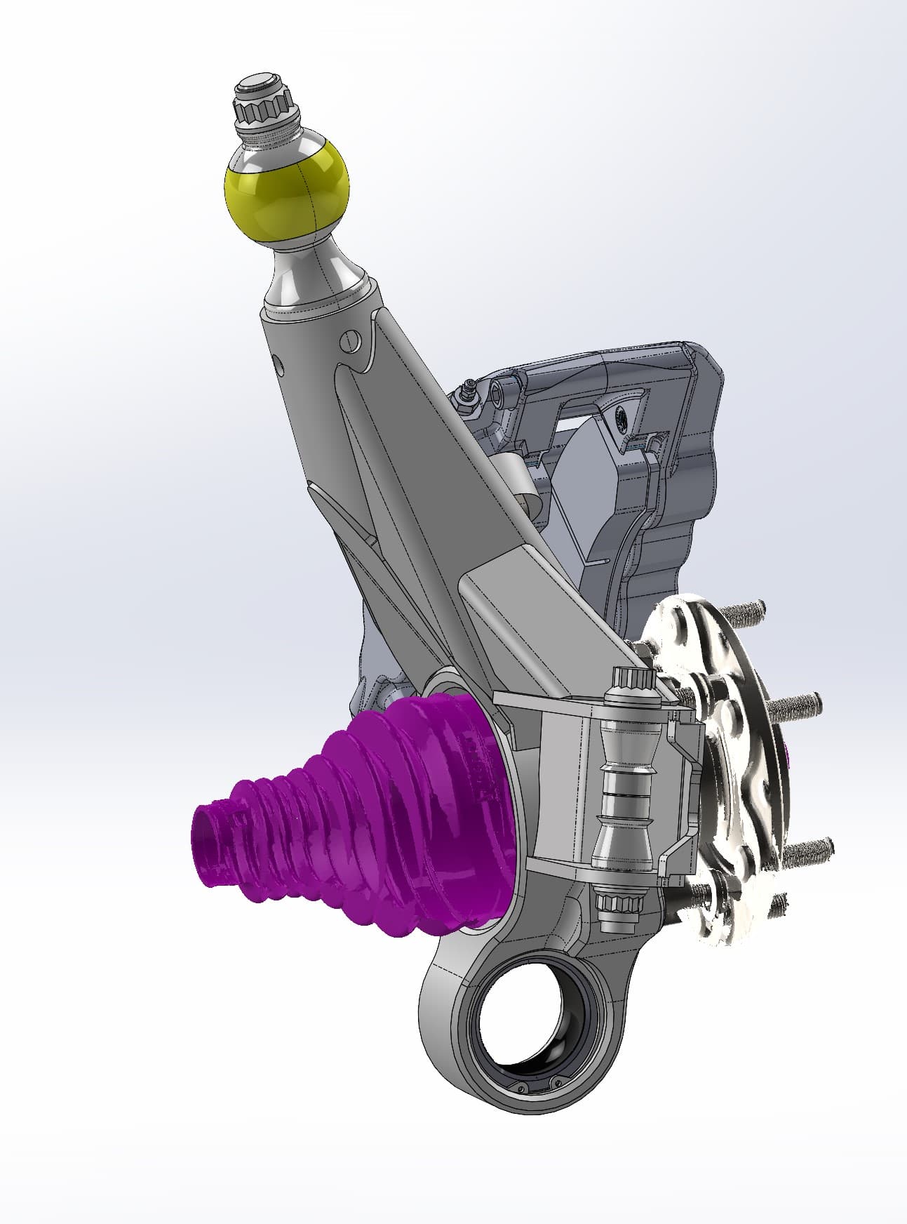
Everything in gray is new. The tubular upper and lower A-arms, the coilover and bypass shocks, the fabricated upright and the brake hardware were all modeled to fit around the colored scan data. You can see ragged mesh edges on the CV boot in the close-ups, a sign that it's the real scanned part and not a modeled approximation.
From scan mesh to a usable steering rack model
A raw scan of a power-steering rack is accurate, but it's heavy and full of detail you don't need in every view. For this job the rack exists three ways: the yellow scan mesh with its hydraulic lines, a detailed CAD model, and a simplified gray model for packaging work.
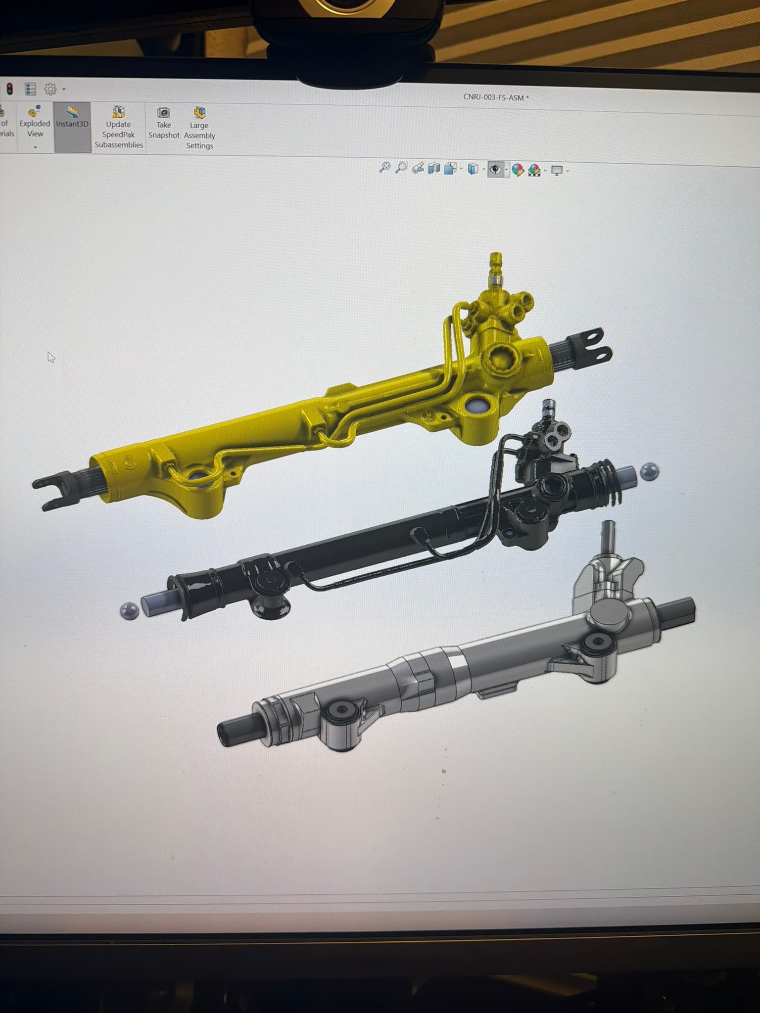
A simplified model keeps a big assembly responsive while you move the suspension through its travel. The scan stays available as the reference for anything that has to fit tight to the real part.
Designing the corner
With the drivetrain and steering fixed in place, the corner came together around them:
- Tubular upper and lower A-arms
- A coilover plus a bypass shock with a remote reservoir
- A custom fabricated upright with a ball joint at the top and a steering rod end
- A hub with five lug studs, a multi-piston caliper on a fabricated bracket and a large slotted, vented rotor
- A tie rod running back to the scanned rack
The scanned CV boot runs into the hub, so the axle angle and boot position can be checked against the real part as the upright moves.
Checking the brake and upright inside the wheel
The last packaging check is the wheel itself. The upright, caliper, rotor and hub were placed inside a see-through tire, so the clearance between the brake package, the upright and the wheel can be read directly in CAD.
What the customer got
- Scan meshes of the factory differential, steering rack and CV boots
- A simplified steering rack model for fast packaging work
- A front suspension assembly in SolidWorks: arms, upright, hub, brake mounting and shocks
- Packaging checks of the brake and upright inside the wheel
Planning a long-travel or IFS build?
The fastest way to a front end that fits is to stop guessing where the factory parts are. Scan the diff, rack and axles, and design around them. Our reverse engineering and scan-to-CAD service covers both the scan and the design, and 3D scanning for motorsports walks through how off-road teams use scan data. See more motorsports work, or get an instant estimate for scanning your drivetrain parts.